Cable release device

a technology of power cable connector and breakaway device, which is applied in the direction of coupling device connection, cable installation on floats, machines/engines, etc., can solve the problems of coupled connectors, inability to de-mated whist hot, and typical unmanned offshore floating structures such as wind turbines

Active Publication Date: 2020-03-26
JDR CABLE SYST
View PDF2 Cites 4 Cited by
  • Summary
  • Abstract
  • Description
  • Claims
  • Application Information

AI Technical Summary

Benefits of technology

[0011]Advantageously, the sharp protrusions are a pair of cutting blades and are pivotally mounted to the body of the cable breakaway device such that a power core of the power cable may pass through the channel of the breakaway device without binding. This allows simpler and safer installation of the breakaway device as the cutting blades do not catch the body of a power core being passed through the breakaway device during installation.
[0020]Favourably, the method further comprises a hang-off assembly having a fixed portion and a detachable portion connected to and supported by the fixed portion by a shear pin, wherein the power cable is connected to the detachable portion to support the power cable, the method comprising: inducing a load between the fixed portion and the detachable portion to cause the shear pin to fail due to the induced load, such that the detachable portion becomes separated from and unsupported by the fixed portion; and allowing the detachable portion to move away from the fixed portion, drawing the cable through the hang-off assembly such that at least a portion of the cable is drawn through the channel as a result of the load in the cable due to the separation of the detachable portion from the fixed portion. In this way, the floating structure can be evacuated or be left unmanned whilst still allowing activation of the separation mechanism.

Problems solved by technology

Offshore floating structures, such as a wind turbine, are typically un-manned and held in position using mooring lines to anchor the floating structure to the seabed.
However, the coupled connectors have the drawback in that they cannot be de-mated whist hot due to the internal expanding of the connection ring that connects the electrical cables to the coupled connectors.
In the event of a mooring line failure, for example due to a storm or a collision between a floating structure or vessel, severe localised damage can be done to both the floating structure and the integrally mounted tubes by the load from the connected, external electrical power cables.
If the securing structure is unable to release the electrical power cables from the deck power cores or whatever connection is provided to the structure, then significant damage may be done to elements of the tubes and or supporting structure some of which may be difficult and / or expensive to repair on site.
If the electrical connector is sufficiently strong, it may prevent the separation of the power cables from the structure which can lead to the damage mentioned above.
This damage can be difficult, time consuming and expensive to repair offshore especially compared to the cost of re-instating the electrical power cable if it is released as desired by the release mechanism.

Method used


Image

  • Cable release device
  • Cable release device
  • Cable release device

Examples


Embodiment Construction

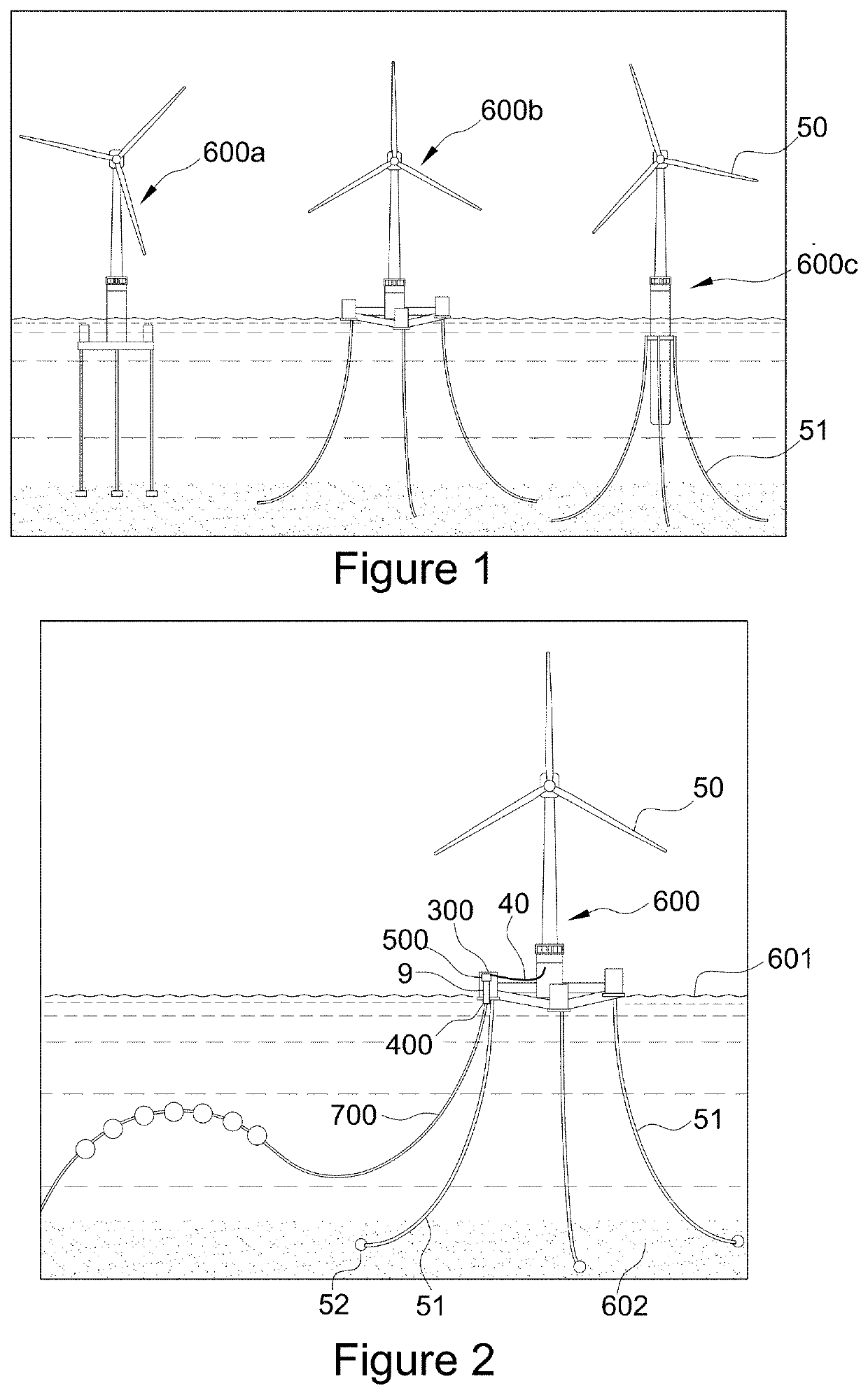
[0032]An embodiment of the invention is described below. This would typically be used with floating structures that need to be connected to an external power connection for the transmission and / or receipt of electrical power. Under some circumstances such structures may require an electrical power cable connection to be rapidly released from the structure such as during a storm or collision event. A typical floating structure layout that might utilise an embodiment of the invention will now be described.

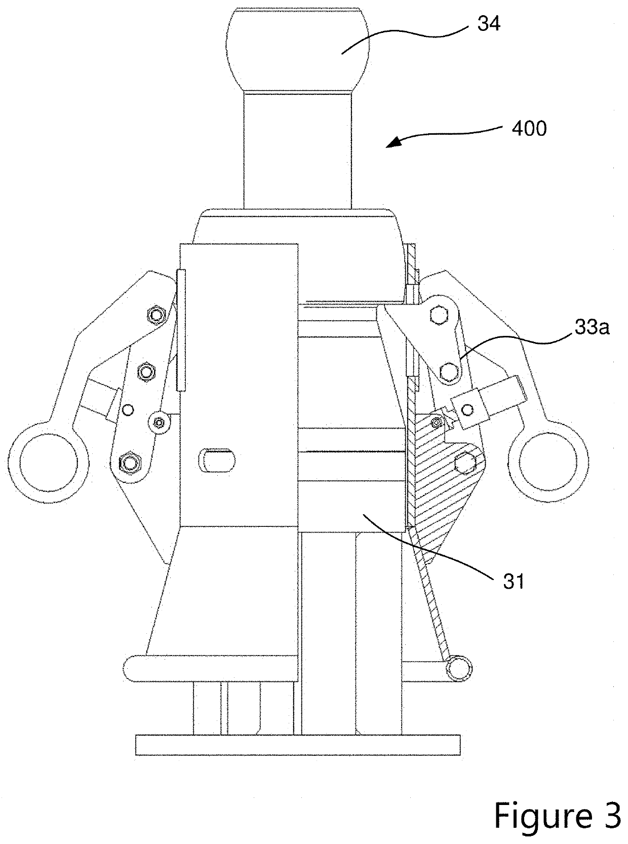
[0033]FIG. 1 shows examples of typical floating structures 600a, 600b, 600c. FIG. 2 shows a floating structure 600 arranged to float on a sea surface 601 and comprises a turbine 50 and mooring lines 51. The mooring lines 51 are used to hold the floating structure 600 in place by using the anchors 52 to anchor the mooring lines 51 to the seabed 602. The floating structure 600 further comprises a tube 9 and deck power cores 40; the tube 9 allows the passage of a power cable 700 which c...


PUM


Abstract

A cable breakaway device for use with a power cable connector and a power cable, the power cable connector comprising a sheath and a bearing surface. The cable breakaway device comprising a body with an elongate channel passing therethrough, one or more sharp protrusions radially extending from the body to cut the sheath as the cable is pulled through the channel, allowing the bearing surface to engage the breakaway device without impeding the movement of the connecting device.

Description

CROSS REFERENCE TO RELATED APPLICATIONS[0001]The present application claims priority to United Kingdom Application No. 1815720.6 filed Sep. 26, 2018, the entirety of the disclosure of which is expressly incorporated herein by reference.STATEMENT RE: FEDERALLY SPONSORED RESEARCH / DEVELOPMENT[0002]Not Applicable.FIELD OF THE INVENTION[0003]This invention relates to a power cable connector emergency breakaway device.BACKGROUND OF THE INVENTION[0004]Offshore floating structures, such as a wind turbine, are typically un-manned and held in position using mooring lines to anchor the floating structure to the seabed. External electrical power cables may then be connected to the power cores on the deck of the floating structure via connectors whereby, the connectors generally are of a T shaped design and interlock with each other to provide a rotationally adjustable routing position. Alternatively, cable connections have been made by hard wiring the electrical cables into a junction box, whic...

Claims


Application Information

Patent Timeline
Patent Type & Authority Applications(United States)
IPC IPC(8): H01R13/502H01R13/622H01R13/64
CPCH01R13/622H01R13/502H01R13/64H02G1/10H02G1/1209H02G9/12E02B17/0017E02B2017/0095F03D80/85H02G1/12H02G9/00H02G15/007
Inventor WARD, PHILIP ALLAN
Owner JDR CABLE SYST
Why Eureka
Try Eureka