
Vacuum cleaning apparatus

Pending Publication Date: 2020-04-02
TOSHIBA LIFESTYLE PROD & SERVICES CORP
View PDF5 Cites 21 Cited by
  • Summary
  • Abstract
  • Description
  • Claims
  • Application Information

AI Technical Summary

Benefits of technology

The vacuum cleaning apparatus described in this patent has a vacuum cleaner that can autonomously travel and a station device that collects the dust and dirt collected by the vacuum cleaner. The vacuum cleaner has a cleaning part that removes dust and dirt, a dust-collecting unit that accumulates the removed substances, a detector that detects the amount of dust and dirt in the unit, and a controller that controls the vacuum cleaner's travel. The controller makes the vacuum cleaner travel to the station device when the amount of dust and dirt collected reaches a certain level, and it makes the vacuum cleaner undock from the station device to restart the cleaning after the collected substances are transferred to the station device. The technical effect of this invention is a more efficient and effective vacuum cleaning system that allows for autonomous travel and real-time detection of the amount of dust and dirt collected.

Problems solved by technology

In this case, it is inconvenient for a user to dispose of the dust and dirt accumulated in the dust-collecting unit every time the cleaning is completed.
Therefore, it is not easy to downsize such a vacuum cleaner while ensuring convenience.
Therefore, a sufficiently-downsized vacuum cleaner is hardly provided.

Method used


Image

  • Vacuum cleaning apparatus
  • Vacuum cleaning apparatus
  • Vacuum cleaning apparatus

Examples


first embodiment

[0016]The configuration of the first embodiment is described below with reference to the drawings.

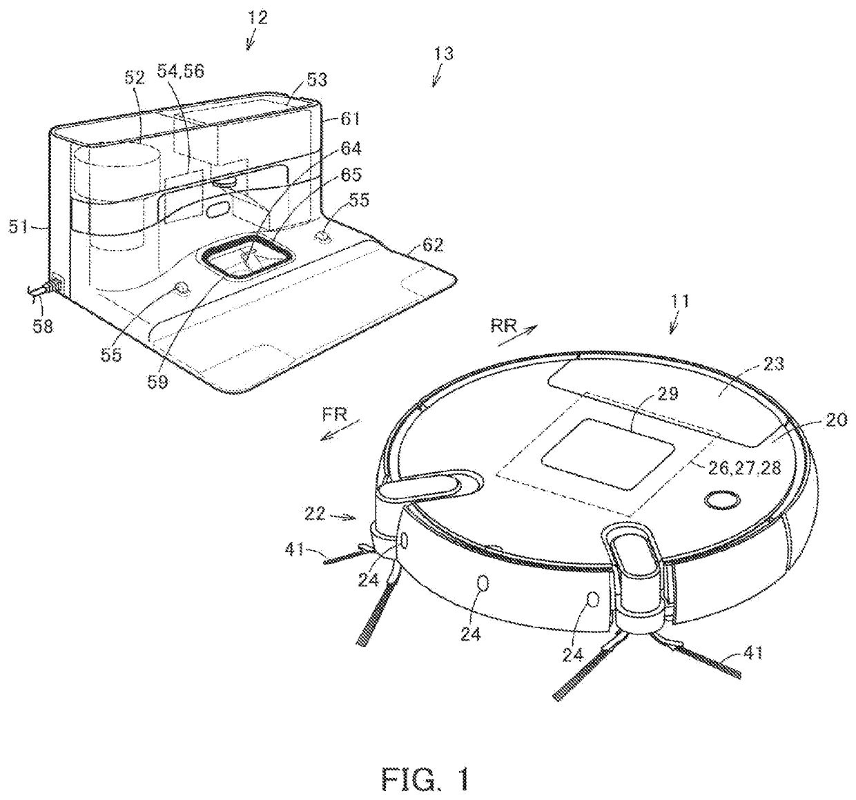
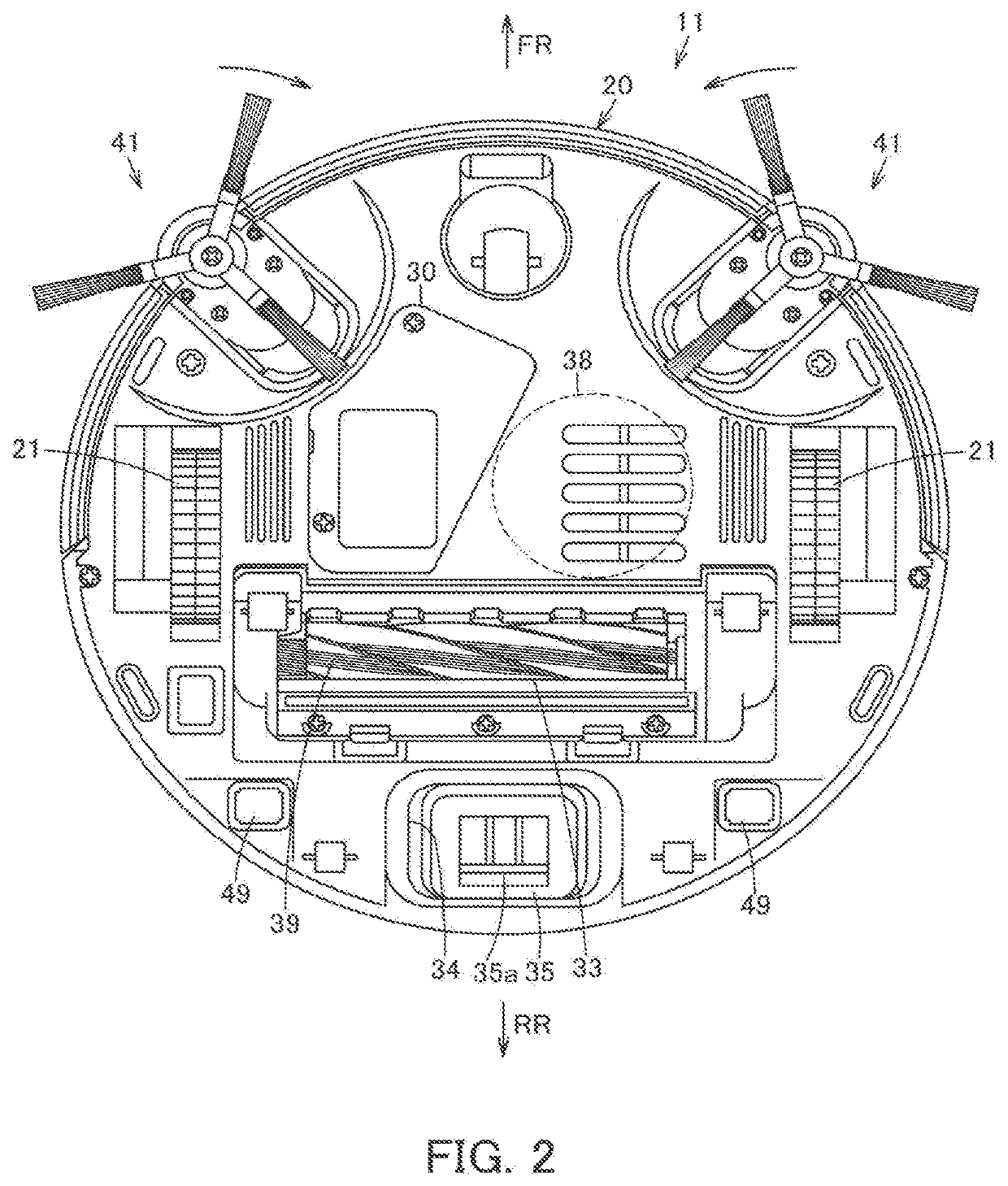
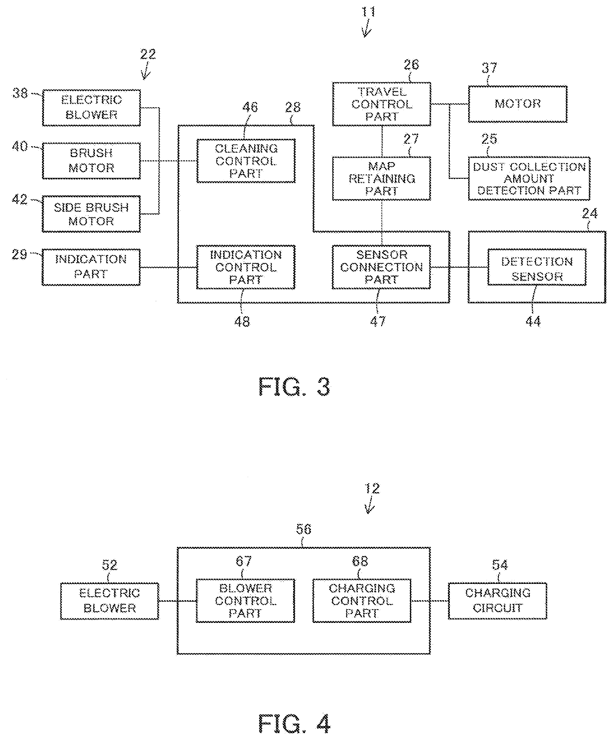
[0017]In FIG. 1 to FIG. 3, reference sign 11 denotes a vacuum cleaner as an autonomous traveler. The vacuum cleaner 11 constitutes a vacuum cleaning apparatus (a vacuum cleaning system) 13 serving as an autonomous traveler device, in combination with a dust station (a charging table) 12 serving as a station device corresponding to abase part for the vacuum cleaner 11. In the present embodiment, the vacuum cleaner 11 is a so-called self-propelled robot cleaner (a cleaning robot), which cleans a floor surface that is a cleaning-object surface as a traveling surface, while autonomously traveling (self-traveling) on the floor surface.

[0018]The vacuum cleaner 11 includes a main casing 20 which is a hollow main body. The vacuum cleaner 11 further includes driving wheels 21 which are travel driving parts. The vacuum cleaner 11 further includes a cleaning unit 22 for removing dust and dirt. The...

second embodiment

[0082]As described above, when the amount of the dust and dirt detected by the dust collection amount detection part 25 is equal to or more than a specified amount and when the travel control part 26 performs control to make the vacuum cleaner 11 travel to the dust station 12, the feature storage part 69 stores the feature of the position P at which the amount of the dust and dirt has been determined to be equal to or more than the specified amount. The travel control part 26 makes the vacuum cleaner 11 travel to the position P at which the amount of the dust and dirt accumulated in the dust-collecting unit 23 has been determined to be equal to or more than the specified amount, on the basis of the stored feature, thereby enabling to make the vacuum cleaner 11 travel smoothly and efficiently to the position P.

[0083]The map of the cleaning area needs not to be retained, and thus the configuration for retaining (storing) the map or the like is not required. Accordingly, a simpler con...


PUM


Abstract

A vacuum cleaner includes a driving wheel, a cleaning part, a dust-collecting unit, a dust collection amount detection part, and a travel control part. The dust collection amount detection part detects the amount of the dust and dirt accumulated in the dust-collecting unit. The travel control part controls the driving of the driving wheel to make the vacuum cleaner travel autonomously. The travel control part makes the vacuum cleaner travel to a dust station in the case the amount of the dust and dirt detected by the dust collection amount detection part is equal to or more than a specified amount while the cleaning part performs cleaning. The travel control part further makes the vacuum cleaner undock from the dust station to restart the cleaning after the dust and dirt accumulated in the dust-collecting unit is transferred to a dust-collecting container at the dust station. The vacuum cleaning apparatus can adopt a downsized vacuum cleaner while ensuring convenience.

Description

TECHNICAL FIELD[0001]Embodiments described herein relate generally to a vacuum cleaning apparatus including a vacuum cleaner and a station device.BACKGROUND ART[0002]Conventionally, a so-called autonomously-traveling type vacuum cleaner (a cleaning robot) has been known, which cleans a cleaning-object surface while autonomously traveling on the cleaning-object surface. The vacuum cleaner incorporates a secondary battery as a power source. The vacuum cleaner constitutes a vacuum cleaning system, in combination with a charging table serving as a station device for charging the secondary battery under a standby state such as after the completion of the cleaning.[0003]This type of vacuum cleaner includes a dust-collecting unit for accumulating the dust and dirt collected and caught from a floor surface as the cleaning-object surface. Some of the vacuum cleaners return to the charging table to complete the cleaning, when the amount of the dust and dirt accumulated in the dust-collecting ...

Claims


Application Information

Patent Timeline
IPC IPC(8): A47L11/40A47L9/00A47L9/14A47L9/28
CPCA47L9/2873A47L2201/04A47L11/4061A47L9/009A47L2201/024A47L11/4011A47L11/4025A47L9/281A47L9/149A47L2201/022A47L9/2852A47L9/19A47L9/28
Inventor MARUTANI, YUUKIWATANABE, KOTA
Owner TOSHIBA LIFESTYLE PROD & SERVICES CORP
Learn More