Eureka AIR delivers breakthrough ideas for toughest innovation challenges, trusted by R&D personnel around the world.

Electrical apparatus

Active Publication Date: 2020-04-02
HONDA MOTOR CO LTD
View PDF0 Cites 0 Cited by
  • Summary
  • Abstract
  • Description
  • Claims
  • Application Information

AI Technical Summary

Benefits of technology

The present invention provides a connector connecting portion on the inner side of the housing, which ensures efficient use of space and protection from external impact. This results in a smaller electrical apparatus size and allows for a large space for the electric circuit unit.

Problems solved by technology

In addition, if the connector connecting portion bulges out from the side surface of the housing, there is a possibility that external impact may be directly input to the connector connecting portion.

Method used


Image

  • Electrical apparatus
  • Electrical apparatus
  • Electrical apparatus

Examples


Embodiment Construction

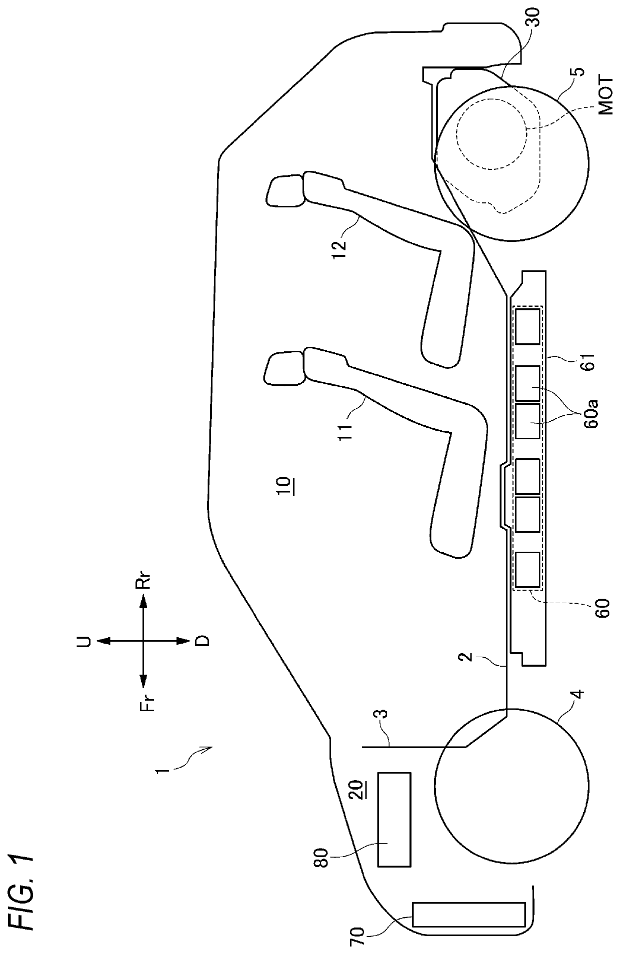
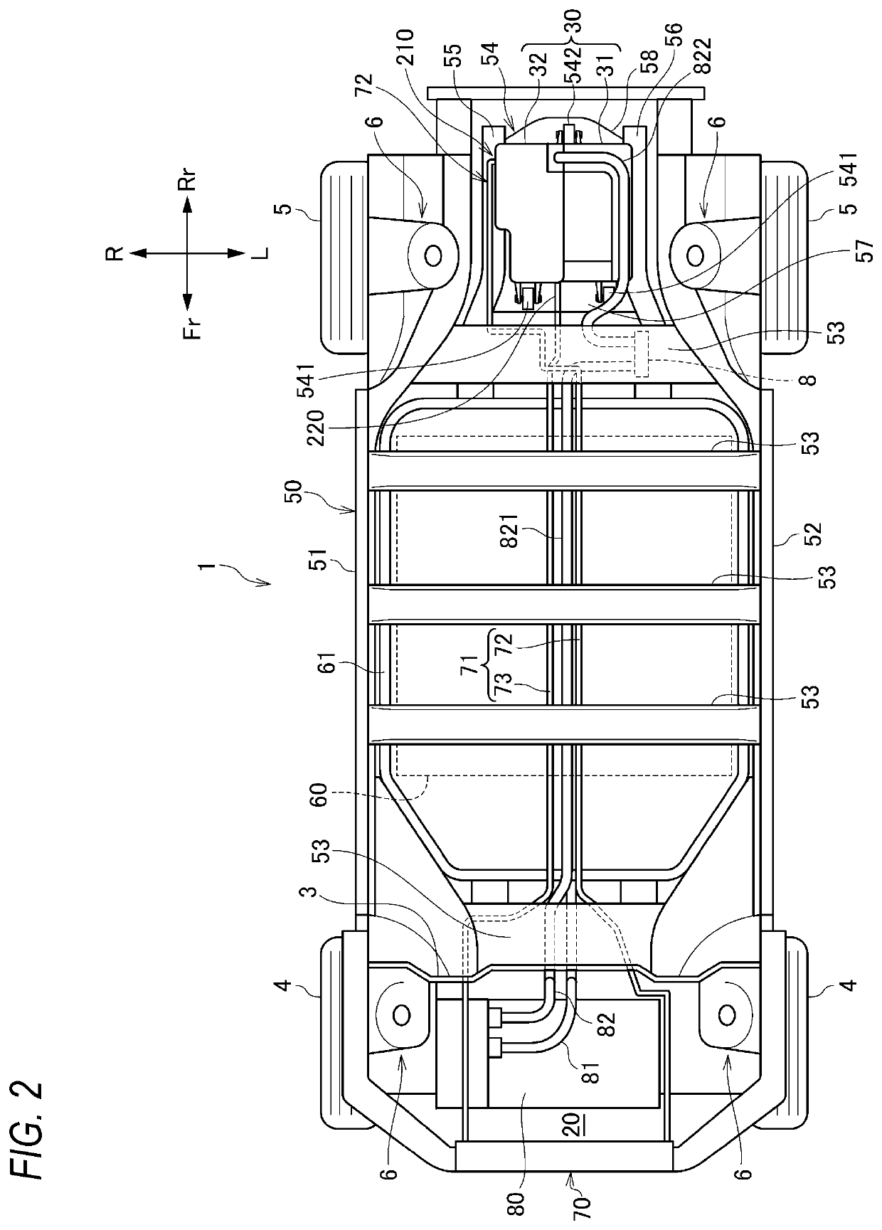
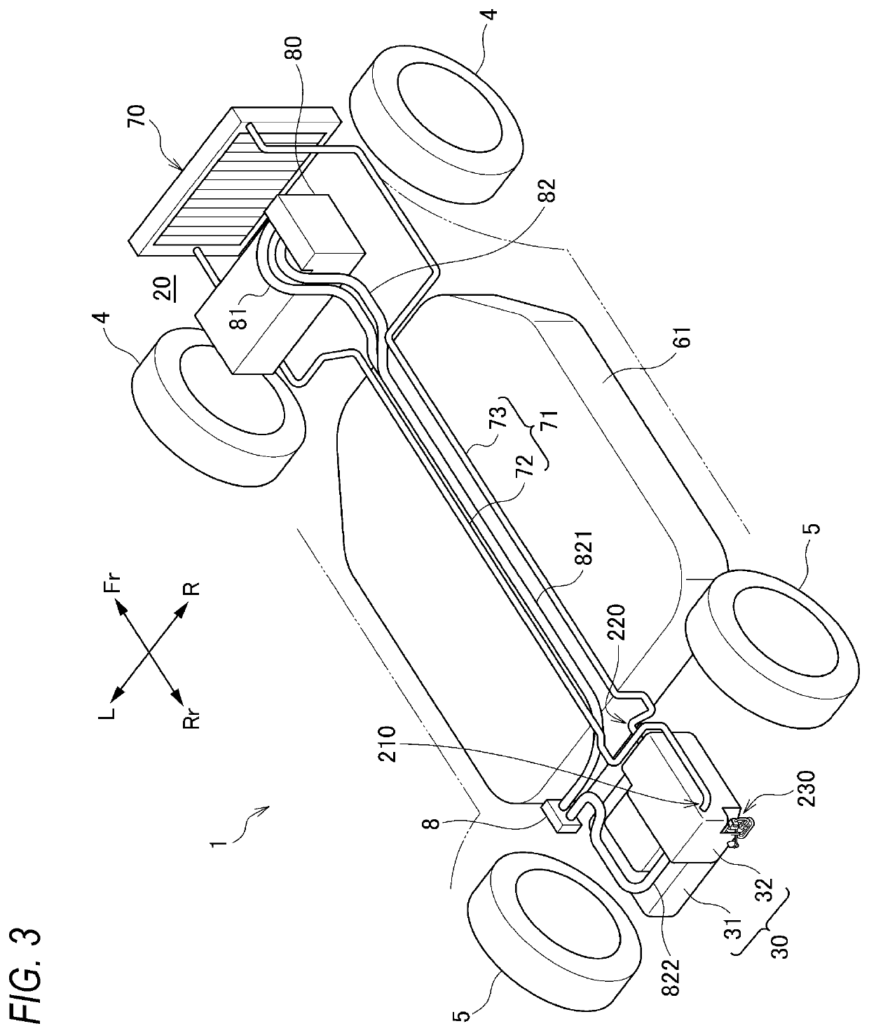
[0025]An electrical apparatus according to an embodiment of the present invention will be described below using an electrical apparatus mounted on a vehicle as an example with reference to the drawings. The drawings should be seen based on a direction of reference numerals. In the following description, front, rear, left, right, upper, and lower directions are described according a view from an operator of the vehicle. In the drawings, a front side of the vehicle is denoted by Fr, a rear side is denoted by Rr, a left side is denoted by L, a right side is denoted by R, an upper side is denoted by U, and a lower side is denoted by D.

[0026][Overall Structure of Vehicle]

[0027]As shown in FIGS. 1 and 2, a vehicle 1 is formed by a vehicle interior 10 and a front room 20 in front of the vehicle interior 10, which are defined by a floor panel 2 and a dash panel 3. Front seats 11 and rear seats 12 are provided in the vehicle interior 10. A driving device unit 30 is provided below the floor p...


PUM


Abstract

A vehicle includes an electrical apparatus comprising an electric circuit unit, a cooling unit that cools the electric circuit unit, a housing that accommodates the electric circuit unit and the cooling unit, a refrigerant introduction unit that supplies a refrigerant to the cooling unit; and a refrigerant discharge unit that discharges the refrigerant from the cooling unit. The refrigerant introduction unit and the refrigerant discharge unit are provided on opposite sides with the electric circuit unit being interposed therebetween in a horizontal direction. The housing is provided, on an inner side of an outer edge of the housing, with a connector connecting portion that is connected to a connector, and the connector connecting portion is provided below the cooling unit and closer to the refrigerant introduction unit or to the refrigerant discharge unit than the electric circuit unit in the horizontal direction.

Description

CROSS-REFERENCE TO RELATED APPLICATIONS[0001]This application is based on and claims priority under 35 USC 119 from Japanese Patent Application No. 2018-187589 filed on Oct. 2, 2018.TECHNICAL FIELD[0002]The present invention relates to an electrical apparatus provided with a connector connecting portion to which a connector is connected.BACKGROUND ART[0003]In the electrical apparatus of JP-A-2014-93379, a connector connecting portion bulges out from a side surface of a housing and a eave portion protruding from an upper end portion of the housing is provided above the connector connecting portion, so that the connector connecting portion is prevented from being flooded.[0004]However, in JP-A-2014-93379, since the connector connecting portion bulges out from the side surface of the housing, the size of the electrical apparatus is increased, and since the eave portion is provided thereon, the size of the electrical apparatus is further increased. In addition, if the connector connecti...

Claims


Application Information

Patent Timeline
IPC IPC(8): B60H1/00
CPCB60H1/00535B60H2001/2278B60H1/00528B60H1/00271B60H1/00428B60L58/26B60L15/007B60L1/003B60L1/02B60L2240/525B60L3/003B60Y2306/01B60K1/00B60K2001/006B60K2001/0438Y02T10/64Y02T10/70H05K7/20927H01L23/473
Inventor TOMINAGA, TAKUROSUZUKI, TAKANORI
Owner HONDA MOTOR CO LTD
Why Eureka
Eureka Blog
Learn More