Diamond based touch sensor panel architectures

a technology of touch sensor and diamond-shaped electrode, which is applied in the field of diamond-shaped touch sensor panel configuration, can solve the problems of troublesome detection of objects (e.g. fingers) further away from the touch sensor panel, and achieve the effects of improving the touch sensing performance of the system, improving optical uniformity, and high precision

Active Publication Date: 2020-04-02
APPLE INC
View PDF0 Cites 7 Cited by
  • Summary
  • Abstract
  • Description
  • Claims
  • Application Information

AI Technical Summary

Benefits of technology

[0005]In some examples, sensing the mutual capacitance of touch electrodes arranged in rows and columns can determine the location of a touch on the touch sensor panel with relatively high precision, but may have trouble detecting objects (e.g., fingers) further away from the touch sensor panel (e.g., hovering over the touch sensor panel). In some examples, sensing the self-capacitance of touch electrodes can effectively detect the locations of one or more objects (e.g., fingers) hovering over and / or touching the touch sensor panels, but touch electrode configurations for use in self-capacitance sensing can require a large number of touch electrodes and routing traces. Therefore, it can be beneficial to combine mutual capacitance and self-capacitance sensing of touch electrodes in a single touch sensor panel. The examples of the disclosure provide various touch sensing system configurations that combine mutual capacitance and self-capacitance sensing of diamond-shaped touch electrodes (e.g., touch electrodes having diamond shapes). Doing so can help can improve the touch sensing performance of the system while improving optical uniformity, reducing the number of electrodes and corresponding routing traces, and can help to decrease and optimize cost and facilitate system integration.

Problems solved by technology

In some examples, sensing the mutual capacitance of touch electrodes arranged in rows and columns can determine the location of a touch on the touch sensor panel with relatively high precision, but may have trouble detecting objects (e.g., fingers) further away from the touch sensor panel (e.g., hovering over the touch sensor panel).

Method used


Image

  • Diamond based touch sensor panel architectures
  • Diamond based touch sensor panel architectures
  • Diamond based touch sensor panel architectures

Examples


Embodiment Construction

[0015]In the following description of examples, reference is made to the accompanying drawings which form a part hereof, and in which it is shown by way of illustration specific examples that can be practiced. It is to be understood that other examples can be used and structural changes can be made without departing from the scope of the disclosed examples.

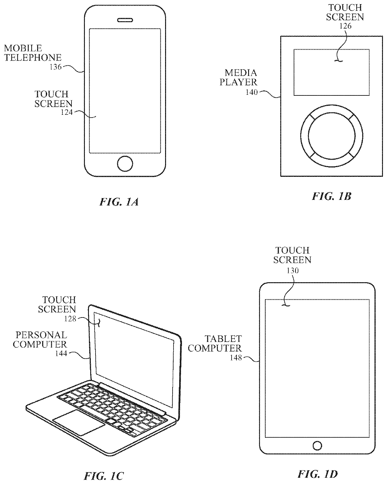
[0016]Described here are capacitive touch sensor panels. Generally, the touch sensor panels comprise a plurality of plates formed from a conductive material; these plates are referred to herein as “touch electrodes.” The touch electrodes may be made from any suitable conductive material (e.g., a transparent conductive oxide such as ITO or aluminum zinc oxide, a metal such as copper, a metal mesh material comprising a conductive cross-hatched metal structure with gaps between cross-hatched metal lines, carbon nanotube material, or any other suitable conductive material), which may be substantially transparent or non-transparent, de...


PUM


Abstract

A touch sensor panel including a first set of touch electrodes configured to operate as drive electrodes and a second set of touch electrodes configured to operate as sense electrodes. The first set of touch electrodes being disposed within gaps between the second set of touch electrodes, and a given row or column of touch electrodes of the second set of touch electrodes includes a plurality of subsets of touch electrodes that are separately addressable by touch sensing circuitry.

Description

CROSS REFERENCE TO RELATED APPLICATIONS[0001]This application claims benefit of U.S. Provisional Patent Application No. 62 / 738,917, filed Sep. 28, 2018, the entire disclosure of which is incorporated herein by reference for all purposes.FIELD OF THE DISCLOSURE[0002]This relates generally to touch sensor panels, and more particularly, to touch sensor panels with diamond-shaped touch electrode configurations.BACKGROUND OF THE DISCLOSURE[0003]Many types of input devices are presently available for performing operations in a computing system, such as buttons or keys, mice, trackballs, joysticks, touch sensor panels, touch screens and the like. Touch screens, in particular, are popular because of their ease and versatility of operation as well as their declining price. Touch screens can include a touch sensor panel, which can be a clear panel with a touch-sensitive surface, and a display device such as a liquid crystal display (LCD), light emitting diode (LED) display, or organic light e...

Claims


Application Information

Patent Timeline
Patent Type & Authority Applications(United States)
IPC IPC(8): G06F3/044G06F1/16G06F3/045
CPCG06F3/044G06F3/045G06F2203/04112G06F2203/04111G06F1/16G06F2203/04107G06F3/04164G06F3/041662G06F3/0443G06F3/0445G06F3/0446G06F3/0448
Inventor VAZE, SAGAR RAJIV
Owner APPLE INC
Why Eureka
Try Eureka