System and Method for Controlling Compounding in a Brake Actuator

a technology of brake actuator and compounding system, which is applied in the direction of braking system, braking components, transportation and packaging, etc., can solve the problems of reducing the life of the brake actuator pushrod and downstream brake components, sacrificing some of the life of the brake actuator components, and adding expense and weight to the vehicle, so as to achieve precise and rapid control of compounding and reduce the cost of compounding. , the effect of increasing the cost and weigh

Active Publication Date: 2020-04-16
BENDIX COMML VEHICLE SYST LLC
View PDF0 Cites 2 Cited by
  • Summary
  • Abstract
  • Description
  • Claims
  • Application Information

AI Technical Summary

Benefits of technology

[0009]A system and method for controlling compounding in a brake actuator of a vehicle in accordance the present teachings represent an improvement as compared to conventional systems and methods. In particular, the system and method enable control of compounding using existing vehicle fluid system components thereby avoiding the need for a special purpose anti-compounding valve. As a result, compounding control can be implemented on vehicles to preserve the life of brake actuator components and other vehicle components without incurring the additional expense and weight of an anti-compounding valve. The inventive system and method also enable more precise and rapid control of compounding and the ability to adjust compounding strategies for different vehicle operating conditions.

Problems solved by technology

The excess force from compounding can reduce the life of the brake actuator pushrod and downstream brake components such as slack adjusters.
Anti-compounding valves, however, add expense and weight to the vehicle.
As a result, many vehicles operate without anti-compounding valves and sacrifice some of the life of components in the brake actuator and downstream components such as slack adjusters.

Method used


Image

  • System and Method for Controlling Compounding in a Brake Actuator
  • System and Method for Controlling Compounding in a Brake Actuator
  • System and Method for Controlling Compounding in a Brake Actuator

Examples


Embodiment Construction

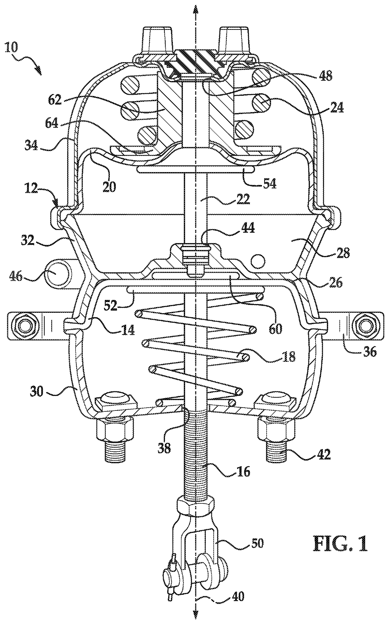
[0014]Referring now to the drawings wherein like reference numerals are used to identify identical components in the various views, FIG. 1 illustrates a conventional brake actuator 10 for a vehicle. Actuator 10 is provided to control actuation and release of brakes associated with one or more vehicle wheels. Actuator 10 may include a housing 12, a service diaphragm 14, a service pushrod 16 movable between a service release position (shown in FIG. 2) and service apply position, a service spring 18, a parking diaphragm 20, a parking pushrod 22 movable between a parking release position (shown in FIG. 2) and a parking apply position, and a parking spring 24.

[0015]Housing 12 provides structural support for the other components of actuator 10 and protects those components from foreign objects and elements. Housing 12 further defines a service brake chamber 26 and a parking brake chamber 28. Housing 22 may include multiple housing members 30, 32, 34. Members 30, 32 together define service...


PUM


Abstract

A system for controlling compounding in a vehicle brake actuator includes first and second valves configured to control, respectively, a first fluid pressure in a parking brake chamber of a brake actuator that acts against a spring force applied by a spring of the actuator to a pushrod of the actuator and a second fluid pressure in a service brake chamber of the actuator that applies a fluid force to the pushrod. A controller is configured to receive first and second fluid pressure signals indicative of the first and second fluid pressures, determine a total brake actuator force applied to the pushrod responsive to the first and second fluid pressure signals and control at least one of the first and second valves responsive to the total brake actuator force to adjust a corresponding one of the first and second fluid pressures and thereby obtain an adjusted total brake actuator force.

Description

BACKGROUND OF THE INVENTIONa. Field of the Invention[0001]This invention relates to a system and method for controlling compounding in a brake actuator of a vehicle. In particular, this invention relates to a system and method for controlling compounding without using an anti-compounding valve.b. Background Art[0002]A conventional vehicle brake actuator generates actuating forces during both service braking and parking or emergency braking. The brake actuator includes a housing defining a service brake chamber and a parking brake chamber. The service brake chamber includes a diaphragm that acts on a pushrod extending from the service brake chamber when fluid pressure is supplied to the service brake chamber in order to set the service brake. The parking brake chamber includes a spring that acts on the same pushrod to set the parking brake and a diaphragm that acts against the spring when fluid pressure is supplied to the parking brake chamber to release the parking brake. In some ci...

Claims


Application Information

Patent Timeline
Patent Type & Authority Applications(United States)
IPC IPC(8): B60T13/68B60T13/58B60T13/22F16D65/16
CPCF16D65/16B60T13/588B60T13/686B60T13/22F16D2121/06B60T17/083B60T13/683
Inventor BOYCE, DANIEL T.HUTCHINS, CHRISTOPHER H.
Owner BENDIX COMML VEHICLE SYST LLC
Why Eureka
Try Eureka