Rotational speed sensor arrangement

Active Publication Date: 2020-06-11
VOLKSWAGEN AG
View PDF0 Cites 5 Cited by
  • Summary
  • Abstract
  • Description
  • Claims
  • Application Information

AI Technical Summary

Benefits of technology

[0011]It is therefore an object of the present invention to provide a rotational speed sensor arrangement, in particular a Hall sensor arrang

Problems solved by technology

Consequently, the number of signal markers that can be distributed over the circ

Method used


Image

  • Rotational speed sensor arrangement
  • Rotational speed sensor arrangement
  • Rotational speed sensor arrangement

Examples


Embodiment Construction

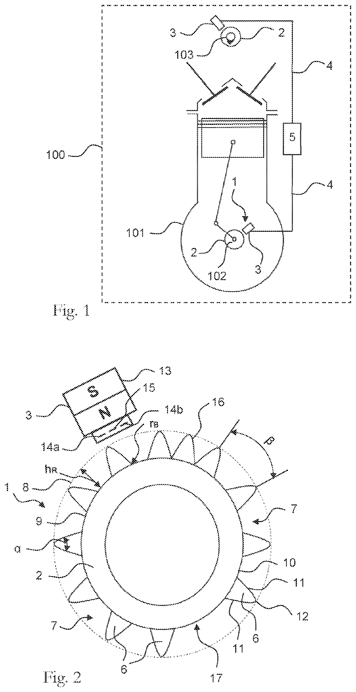
[0036]FIG. 1 schematically shows an exemplary embodiment of a motor vehicle 100 according to the invention with an internal combustion engine 101 that includes a drive shaft arrangement with a crankshaft 102 and a camshaft 103. The crankshaft 102 and the camshaft 103 each have arranged thereupon a rotational speed sensor arrangement 1 that includes a transmitter wheel 2 and a sensor 3 implemented as a differential Hall sensor. Each of the rotational speed sensor arrangements 1 is suitable for sensing both the position and the rotational speed of the crankshaft 102 or the camshaft 103, and for delivering a corresponding output signal through a data line 4 to an engine control unit 5, which controls various motor functions on the basis of the signals, in particular the adjustment of a camshaft adjuster.

[0037]The structure and function of the rotational speed sensor arrangement 1 is described on the basis of FIG. 2. The rotational speed sensor arrangement 1 includes the transmitter whe...


PUM


Abstract

A rotational speed sensor arrangement is provided that includes a transmitter wheel, which has signal markers that are spaced apart from one another; a sensor with at least two Hall sensor elements that form a differential Hall sensor and that each output a Hall signal as a function of the position and/or motion of the signal markers; and a signal circuit that determines an output signal based on the Hall signal, and defines a rotational position of the transmitter wheel based on the output signal, wherein the signal markers have radially extending tooth elements with two switching flanks, and the switching flanks converge in a switching edge. A drive shaft arrangement, an internal combustion engine, and a motor vehicle are also provided.

Description

[0001]This nonprovisional application is a continuation of International Application No. PCT / EP2018 / 069606, which was filed on Jul. 19, 2018, and which claims priority to German Patent Application No. 10 2017 214 166.2, which was filed in Germany on Aug. 14, 2017, and which are both herein incorporated by referenceBACKGROUND OF THE INVENTIONField of the Invention[0002]The present invention relates to a rotational speed sensor arrangement in which a transmitter wheel acts on a differential Hall sensor, and a signal circuit determines, based on a Hall signal, an output signal that indicates a rotational position and / or a rotational motion of the transmitter wheel.Description of the Background Art[0003]A variety of rotational speed sensors exist that are used to sense motor speeds; they are also called speed transmitters, and are necessary for modern engine management. They serve to determine the motor speed, to sense the angular position of the crankshaft (position of the pistons), an...

Claims


Application Information

Patent Timeline
IPC IPC(8): G01P3/488G01D5/14G01P13/04
CPCG01P3/488G01D5/147G01P13/045
Inventor FRICKE, JENSHERRMANN, JULIANBOESEKE, MICHAELMATTEG, INES
Owner VOLKSWAGEN AG
Why Eureka
Try Eureka