Single-pump hydraulic system used for forklift

A hydraulic system and single-pump technology, applied in fluid pressure actuators, lifting devices, servo motors, etc., can solve the problems of inaccurate speed regulation range, rough reversing positioning accuracy, increased engine fuel consumption, etc., and achieve system components Compact, low cost of installation and use, conducive to the effect of compactness

Active Publication Date: 2016-02-17
ANHUI HECHA FORKELEVATOR
7 Cites 3 Cited by

AI-Extracted Technical Summary

Problems solved by technology

This method combines the two aspects. Under the rated load, the efficiency of the system is low, the degree of automation is scattered, the speed regulation ra...

Method used

A kind of forklift single-pump hydraulic system provided by the present embodiment is driven by the engine gear pump 4 to inhale the hydraulic oil from the hydraulic oil tank 5, and discharge the high-pressure oil, which is input into the multi-way reversing valve 6 through the high-pressure rubber hose, and then The multi-way reversing valve 6 is distributed to each actuator, namely: the tilt cylinder 2, the one-way flow limiting valve 11 to the lifting cylinder 1, and the full hydraul...

Abstract

The invention discloses a single-pump hydraulic system used for a forklift. The single-pump hydraulic system comprises a hoist cylinder, an oblique cylinder, a steering cylinder and a gear pump which is used for supplying high-pressure oil fluid to the hoist cylinder, the oblique cylinder and the steering cylinder; the single-pump hydraulic system further comprises a hydraulic oil tank, a multi-way reversing valve and a full-hydraulic steering gear; the oil inlet end of the gear pump is connected with the oil outlet end of the hydraulic oil tank; the oil outlet end of the gear pump is connected with the multi-way reversing valve; the multi-way reversing valve is connected with the oil return end of the hydraulic oil tank; the hoist cylinder, the oblique cylinder and the steering cylinder are all connected with the multi-way reversing valve; and the full-hydraulic steering gear is connected between the multi-way steering valve and the steering cylinder. According to the single-pump hydraulic system used for the forklift disclosed by the invention, the production and manufacture cost is lowered; the operation is more convenient and comfortable; and the production efficiency is improved.

Application Domain

ServomotorsLifting devices

Technology Topic

Gear pumpHigh pressure +4

Image

  • Single-pump hydraulic system used for forklift

Examples

  • Experimental program(1)

Example Embodiment

[0029] The content of the present invention will be described below in conjunction with specific embodiments.
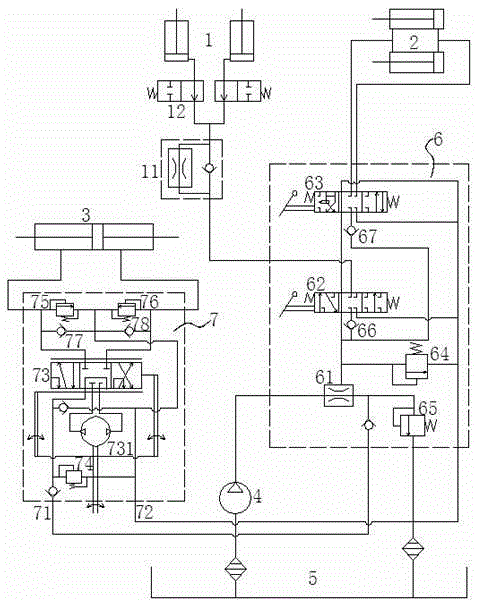
[0030] Such as figure 1 As shown, this embodiment provides a schematic structural diagram of a single-pump hydraulic system for a forklift.
[0031] This embodiment provides a single-pump hydraulic system for a forklift, including a lifting cylinder 1, a tilt cylinder 2, and a steering cylinder 3, and a gear pump 4 that provides high pressure oil for the lifting cylinder 1, the tilt cylinder 2 and the steering cylinder 3; The hydraulic oil tank 5, the multi-way reversing valve 6 and the full hydraulic steering gear 7, the oil inlet end of the gear pump 4 is connected to the oil outlet end of the hydraulic oil tank 5, the oil outlet end of the gear pump 4 is connected to the multi-way reversing valve 6, and more The way reversing valve 6 is connected to the oil return end of the hydraulic oil tank 5. The lifting cylinder 1, the tilt cylinder 2 and the steering cylinder 3 are all connected to the multi-way reversing valve 6, and the multi-way reversing valve 6 is connected to the steering cylinder 3. A full hydraulic steering gear 7 is also connected between.
[0032] The multi-way reversing valve 6 includes a three-way restrictor valve 61, a first directional control valve 62 that controls the lifting cylinder 1, a second directional control valve 63 that controls the tilt cylinder 2, and a full hydraulic steering gear 7 includes an input The oil end 71, the input oil return end 72; the three-way restrictor valve 61 includes an input end and two output ends: the input end of the three-way restrictor valve 61 is connected to the output end of the gear pump 4; The output terminal one is connected to the first directional control valve 62 and the second directional control valve 63 in turn, and then connected in parallel with the input return end 72 of the full hydraulic steering gear 7 to the return end of the hydraulic oil tank 5; the three-way restrictor valve 61 The second output end is connected to the input oil inlet 71 of the full hydraulic steering gear 7; the lifting cylinder 1 is connected to the first directional control valve 62, and the tilt cylinder 2 is connected to the second directional control valve 63.
[0033] Further, the output end one of the three-way flow limiting valve 61 is also connected to the oil return end of the hydraulic oil tank 5 through the first relief valve 64, and the first directional control valve 62 and the second directional control valve 63 are connected in series with the first relief valve. The flow valve 64 is connected in parallel, and the first relief valve 64 and the full hydraulic steering gear 7 are also connected in parallel. The second output end of the three-way limiting valve 61 is also connected to the oil return end of the hydraulic oil tank 5 through a second relief valve 65, and the second relief valve 65 is connected in parallel with the full hydraulic steering gear 7. A one-way flow limiting valve 11 is provided between the lifting cylinder 1 and the first directional control valve 62, and a shutoff valve 12 is also provided between the one-way flow limiting valve 11 and the lifting cylinder 1. The output end one of the three-way flow limiting valve 61 also passes through the first one-way valve 66 and the second one-way valve 67 connected in parallel, respectively, the first direction control valve 62 and the second direction control valve 63.
[0034] The full hydraulic steering gear 7 includes a third direction control valve 73, a third relief valve 74 which is arranged between the input oil inlet 71 and the input oil return end 72 of the full hydraulic steering gear 7 and is connected in parallel with the third direction control valve 73 It also includes a fourth relief valve 75, a fifth relief valve 76, a third one-way valve 77 and a fourth one-way valve 78 arranged between the third-direction control valve 73 and the steering cylinder 3. Specifically, a bidirectional quantitative pump 731 is provided on the third-direction control valve 73.
[0035] This embodiment provides a single-pump hydraulic system for a forklift. The gear pump 4 is driven by an engine to suck hydraulic oil from a hydraulic oil tank 5, discharge high-pressure oil, and input it to the multi-way reversing valve 6 through a high-pressure hose, and then the multi-way The reversing valve 6 is allocated to each actuator, namely: the tilt cylinder 2, the one-way flow limiting valve 11 to the lifting cylinder 1, the full hydraulic steering gear 7 to the steering cylinder 3; the multi-way reversing valve 6 returns to the main oil return outlet and The hydraulic oil tank 5 communicates, so that low-pressure oil flows back. Among them, the oil return port of the full hydraulic steering gear 7 and the integrated oil return port of the multi-way reversing valve 6 are connected by a low-pressure pipeline, so the oil circuit layout is reasonable, efficiency is improved, and losses are reduced.
[0036] During installation, the oil suction port of the gear pump 4 sucks in hydraulic oil from the hydraulic oil tank 5 through the suction pipe and the straight joint, and outputs the high pressure hydraulic oil to the right angle joint of the multi-way reversing valve 6 through the outlet oil pump joint and the high-pressure hose. The operating system branch of the valve 6 is connected to the one-way restrictor valve 11 through the straight pipe joint and the speed of the lifting cylinder 1; the branch two controls the straight pipe joint, the tilt cylinder steel pipe assembly to the tilt cylinder 2 connected with the high pressure hose; branch three The control is connected to the full hydraulic steering gear 7 through the output port high-pressure hose and right-angle joint, and then connected through the right-angle joint and the straight-through joint that communicates with the steering cylinder 3 through the right-angle joint and high-pressure hose. The multi-way reversing valve is connected with 6 points of oil return ports. The above three oil passages flow back to the hydraulic oil tank 5 through the oil return main outlet of the multi-way reversing valve 6.
[0037] The multi-way reversing valve 6 is a hydraulic control valve group composed of a plurality of one-way valves, relief valves and directional control valves. The valve has simple structure, small leakage, good opening and closing characteristics, valve sliding function in various forms, reliable fixed reset method, good valve stem stiffness, high shape and position accuracy, reduced matching clearance, and reduced valve stem diameter. Can reduce the internal leakage of the valve.
[0038] The full hydraulic steering gear 7 can reduce the cost of the main engine, provide a reliable and portable structure, is flexible and portable, safe and reliable, and can perform continuous stepless control rotation with a small torque, providing a wide range of options for the control circuit and the main engine.
[0039] The oil circuit is in the form of a single oil circuit, the space arrangement of the pipeline mechanism becomes simple, and the leakage and pipeline vibration caused by the pipeline connection are reduced.
[0040] The single-pump hydraulic system for forklifts provided in this embodiment enables the multi-way directional valve to meet the requirements of high pressure and large flow in terms of structural design, process performance, etc.; its load feedback sensitivity is high, and it can achieve high-precision control characteristics. The anti-interference ability; through optimized design, the valve body is reasonably arranged; reliable pressure sensitive transmission, pressure compensation mechanism can adapt to various special requirements such as rapid work and sequential confluence mechanism, and the operating mechanism meets the requirements of new full hydraulic hydraulic proportional control. Good micro-motion performance and high-efficiency energy-saving features, in which there is almost no pressure loss, so that the entire system is in a low-pressure standby state. When reversing, the flow rate provided by the oil source is the flow rate required by the actuator. The energy loss can be reduced.
[0041] The above content is a detailed description of the present invention in conjunction with specific embodiments, and it cannot be considered that the specific implementation of the present invention is limited to these descriptions. For those skilled in the art to which the present invention pertains, without departing from the concept of the present invention, several simple deductions or substitutions can be made, which should be regarded as falling within the protection scope of the present invention.

PUM

no PUM

Description & Claims & Application Information

We can also present the details of the Description, Claims and Application information to help users get a comprehensive understanding of the technical details of the patent, such as background art, summary of invention, brief description of drawings, description of embodiments, and other original content. On the other hand, users can also determine the specific scope of protection of the technology through the list of claims; as well as understand the changes in the life cycle of the technology with the presentation of the patent timeline. Login to view more.

Similar technology patents

Container

ActiveUS7137527B2easily configuregood operability
Owner:KOTOBUKI & CO LTD

Gene recombined virus of human neurenergen 3

ActiveCN1958788AHigh transfection rateGood operability
Owner:GUANGZHOU DOUBLLE BIOPRODUCT CO LTD

Fabricated underground diaphragm wall

InactiveCN110499752AGood operabilityConnection quality is reliable
Owner:SHENYANG JIANZHU UNIVERSITY

Classification and recommendation of technical efficacy words

  • good operability

Process for preparing 5-methyl-2-furfural

InactiveUS20070078273A1high yieldgood operability
Owner:SUMITOMO CHEM CO LTD

Vehicle door opening-closing apparatus

ActiveUS20090120001A1good operabilityhigh resistance change
Owner:AISIN SEIKI KK

Novel calcium titanate slag system flux-cored wire and preparation method thereof

ActiveCN102717208Agood operabilityreduce splash
Owner:江苏孚尔姆焊业股份有限公司

Negative terminal and electric connector using the same negative terminal

InactiveCN1773778AGood operabilityNot easy to reverse
Owner:TYCO ELECTRONICS JAPAN GK
Why Eureka
Try Eureka