Apparatus and method for distributing a flushing gas

a technology of flushing gas and apparatus, which is applied in the direction of indirect heat exchangers, drying machines, lighting and heating apparatus, etc., can solve the problems of insufficient removal of undesirable gases from containers, laminar or turbulent flow properties, and insufficient laminar flow rate, so as to preserve the structural integrity of the plate and minimize the occurren

Active Publication Date: 2020-04-16
NOWACZYK DAVID
View PDF0 Cites 0 Cited by
  • Summary
  • Abstract
  • Description
  • Claims
  • Application Information

AI Technical Summary

Benefits of technology

[0006]This invention relates generally to the distribution of a flushing gas during a packaging process. More specifically, the invention relates to a plenum for the distribution of a flushing gas that displaces an undesirable gas from a packaging container during such a process, the plenum optimizing the displacement of the undesirable gas within the container while also minimizing associated equipment costs and cleaning efforts. A plenum is operably associated with a conveyor segment configured for moving a plurality of containers located thereon. Each container defines an open upper end and closed lower end to accommodate the placement of product within each container's interior. The plenum is preferably located proximal to and above the container's open upper ends such that the plenum can flush the containers' interiors with a flushing gas.
[0007]For a plenum configured to provide a turbulent flushing gas flow to the container, the plenum preferably comprises a longitudinal manifold defining a fillister and an inlet for receiving the flushing gas from a pressurized gas source, with the fillister defining an external perimeter flange. A longitudinal covering plate is in sealing abutment with the external perimeter flange to define a longitudinal duct for accommodating the flushing gas therein. The covering plate preferably defines a plurality of through slits that are in fluid communication with the duct. The slits are preferably oriented on an angle in relation to a longitudinal outer edge of the plate to both preserve the structural integrity of the plate and to minimize the occurrence of a container's upper end catching on a slit while carried there-under on the conveyor.
[0009]A longitudinal covering plate is in sealing abutment with the external perimeter flange to define a second longitudinal duct, also for accommodating the flushing gas 50 therein. The covering plate defines a plurality of through slits there-along that are in fluid communication with the second duct. The slits are preferably oriented on an angle in relation to a longitudinal outer edge of the plate to both preserve the structural integrity of the plate and to minimize the occurrence of a container's upper end catching on a slit while carried there-under on the conveyor. In a preferred embodiment, the through slits of the covering plate define a total predetermined cross sectional area that is greater than a total predetermined cross sectional area defined by the at least one through orifice of the dividing plate.

Problems solved by technology

This is because undesirable, atmospheric gases, such as residual oxygen, typically do not inhibit the grown of mold or bacteria within the product, or inhibit the product's oxidation.
To facilitate the displacement of undesirable gases from food product containers during packaging operations, complications arise due to the laminar or turbulent flow properties associated with flushing processes.
For example, a low velocity, laminar flow rate of flushing gases into an empty container, prior to placement of any food product therein, is generally insufficient to remove undesirable gases from the container.
A low velocity flow of flushing gas into the container often allows pockets of undesirable gases to remain therein.
Similarly, a high velocity, turbulent flow rate of flushing gases into a container having the product already placed therein, generally results in a disturbance of the product itself (i.e., an undesirable blowing of the granulated product from within the container).
However, such screen assemblies present numerous disadvantages within the prior art.
For example, screen assemblies contaminate quickly and are difficult to clean, thus presenting increased maintenance and cleaning costs.
Furthermore, screening assemblies often lack rigidity and thus require additional, rigidity-providing materials in their construction—again driving up costs.

Method used


Image

  • Apparatus and method for distributing a flushing gas
  • Apparatus and method for distributing a flushing gas
  • Apparatus and method for distributing a flushing gas

Examples


Embodiment Construction

[0022]This invention relates generally to the distribution of a flushing gas during a packaging process. More specifically, the invention relates to a plenum for the distribution of a flushing gas that displaces an undesirable gas from a packaging container during such a process, the plenum optimizing the displacement of the undesirable gas within the container while also minimizing associated equipment costs and cleaning efforts.

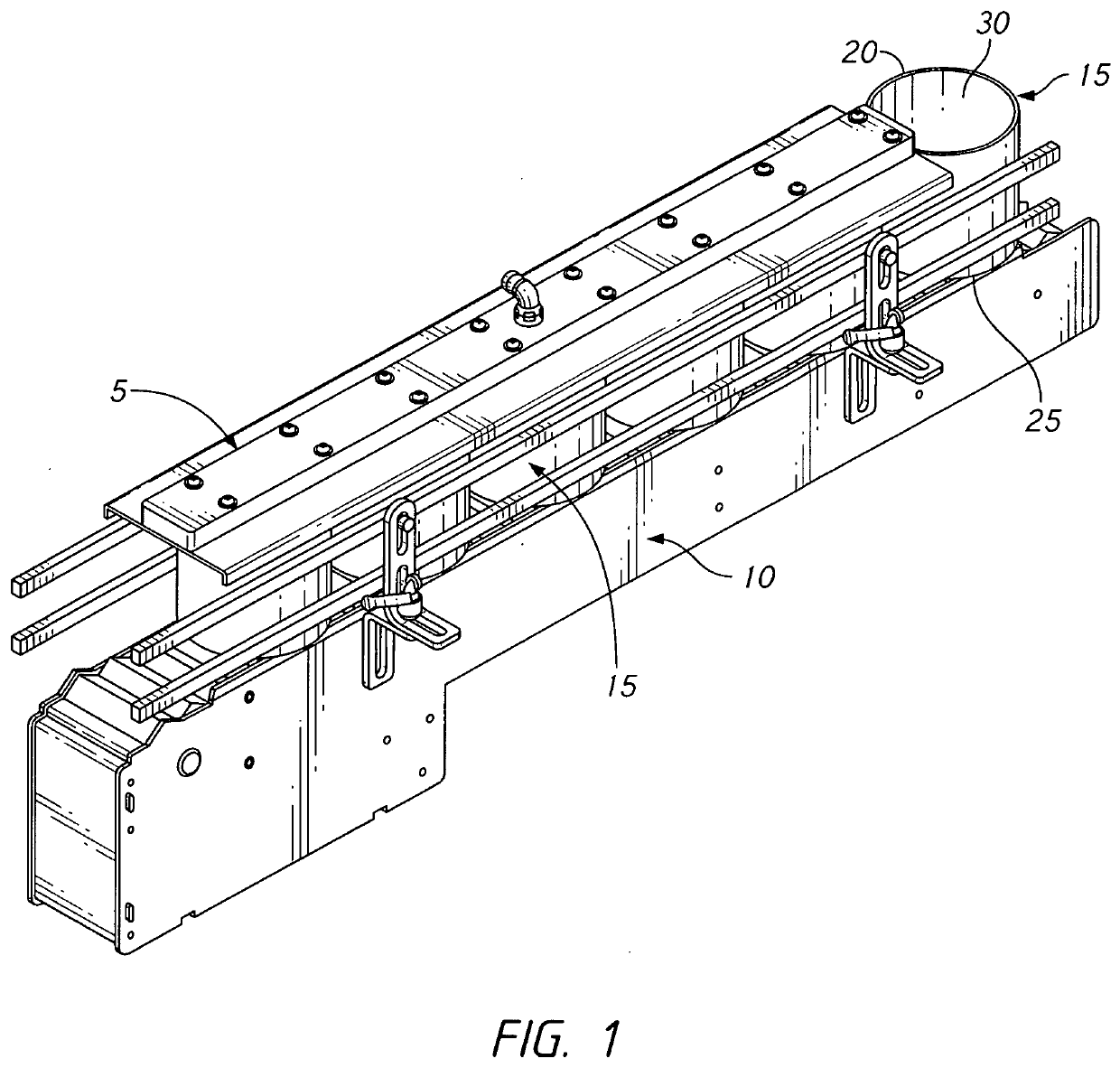
[0023]Referring to FIG. 1 for context, plenum 5 is operably associated with a conveyor segment 10 configured for moving a plurality of containers 15 located thereon. Each container defines an open upper end 20 and closed lower end 25 to accommodate the placement of product within each container's interior 30. Plenum 5 is preferably located proximal to and above the containers' open upper ends 20 such that the plenum can flush the containers' interiors with a flushing gas 50, to be further discussed. The plenum 5 is preferably comprised of polished, stainles...


PUM


Abstract

This invention relates generally to the distribution of a flushing gas during a packaging process. More specifically, the invention relates to an apparatus and method for the distribution of a flushing gas that displaces an undesirable gas from a packaging container during such a process, the apparatus and method optimizing the displacement of the undesirable gas within the container while also minimizing associated equipment costs and cleaning efforts.

Description

CROSS REFERENCE TO RELATED APPLICATIONS[0001]This application claims priority to U.S. Provisional Patent Application Ser. No. 62 / 665,022 having a filing date of May 1, 2018.TECHNICAL FIELD OF THE INVENTION[0002]This invention relates generally to the distribution of a flushing gas during a packaging process. More specifically, the invention relates to an apparatus and method for the distribution of a flushing gas that displaces an undesirable gas from a packaging container during such a process, the apparatus and method optimizing the displacement of the undesirable gas within the container while also minimizing associated equipment costs and cleaning efforts.BACKGROUND OF THE INVENTION[0003]Various food products are packaged within containers such that the freshness of the product is controlled and maintained via a minimization of the product's exposure to undesirable, atmospheric gases. This is because undesirable, atmospheric gases, such as residual oxygen, typically do not inhib...

Claims


Application Information

Patent Timeline
Patent Type & Authority Applications(United States)
IPC IPC(8): B65B31/04
CPCB65B31/041B65B31/00F26B21/00F28D2021/0042F28F9/0221
Inventor NOWACZYK, DAVID
Owner NOWACZYK DAVID
Why Eureka
Try Eureka