Snapshot Ellipsometer

a technology of ellipsometer and ellipsometer, which is applied in the field of spectroscopic ellipsometer, can solve the problem of not being able to fully characterize a sample, and achieve the effect of affecting spectral or spatial characteristics

Active Publication Date: 2020-04-16
J A WOOLLAM CO
View PDF21 Cites 3 Cited by
  • Summary
  • Abstract
  • Description
  • Claims
  • Application Information

AI Technical Summary

Benefits of technology

[0079]Said ellipsometer can provide that an angle of incidence of said beam of electromagnetic radiation to a surface of said sample (5) is adjustable via a mechanism that moves some or all of the optics of the ellipsometer with respect to

Problems solved by technology

This method allows snapshot measurements, but

Method used


Image

  • Snapshot Ellipsometer
  • Snapshot Ellipsometer
  • Snapshot Ellipsometer

Examples


Embodiment Construction

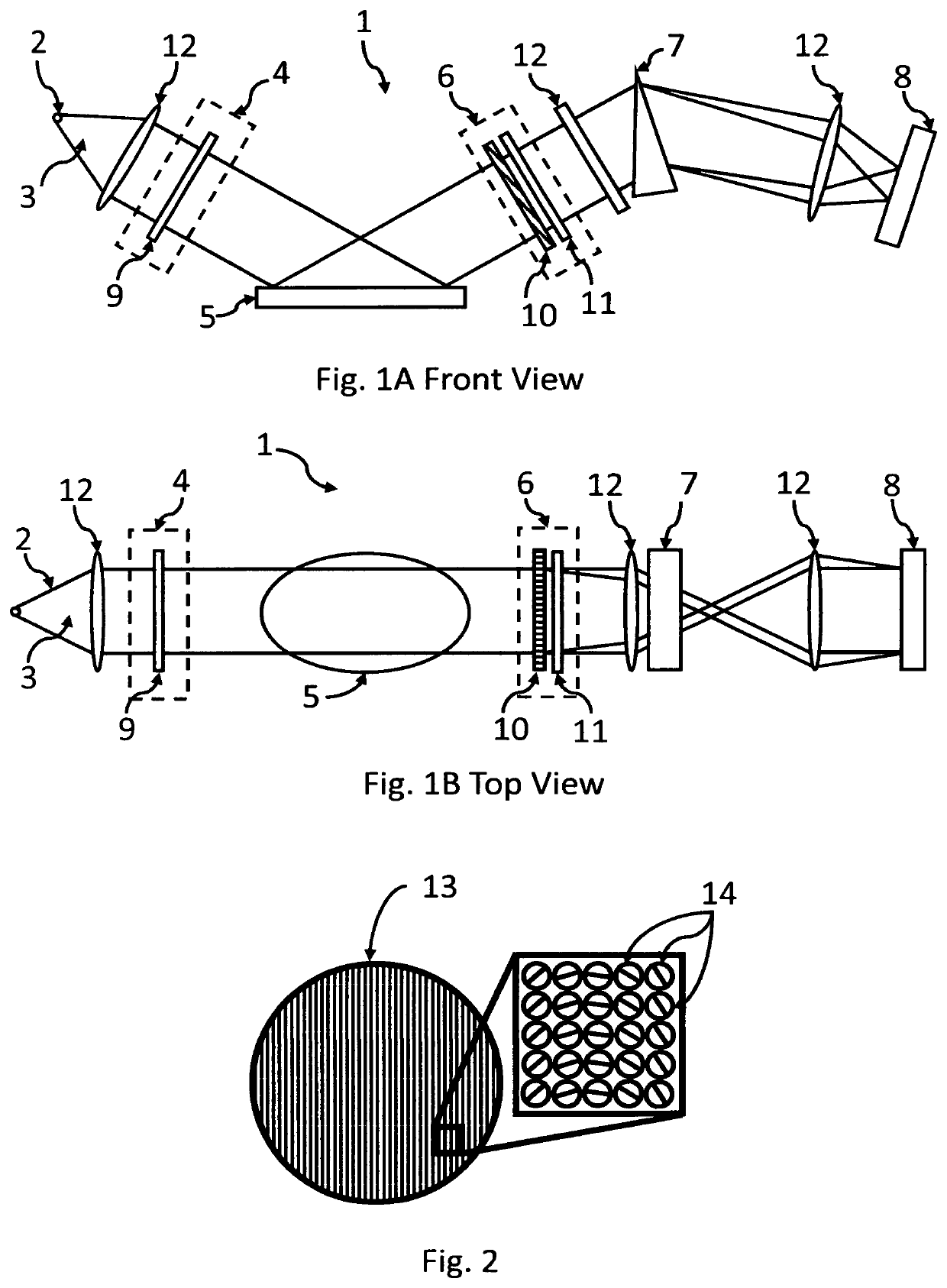
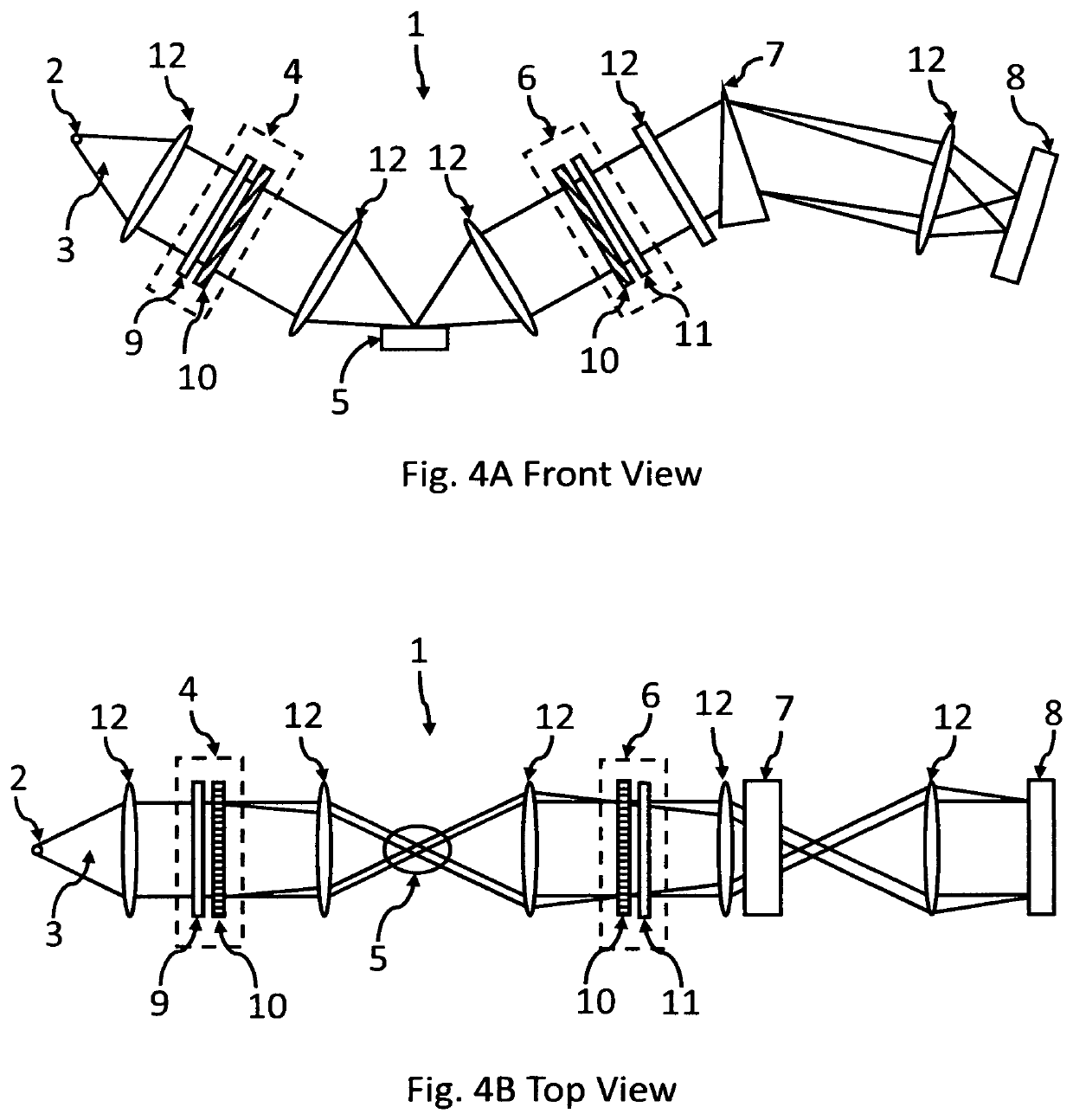
[0121]Turning now to the Drawings, a preferred embodiment of a present invention ellipsometer (1) is shown in FIG. 1. The preferred embodiment includes a source (2) that generates a beam of electromagnetic radiation (3). Said beam of electromagnetic radiation (3) is caused to interact with a polarization state generator (4) which is comprised of at least a single polarizer (9), to create a known polarization state before interacting with a sample (5). The beam then interacts with a polarization state analyzer (6), comprised of a spatially varying compensator (10) and an analyzer (9) causing the beam to have a spatial distribution of intensity along one dimension. (Note, Analyzers and Polarizers are the same the type of elements, with the distinction being that they are deployed on source and detector sides of a sample, respectively, in an ellipsometer). A wavelength separating element (7) such as a dispersion prism or diffraction grating serves to separate the individual wavelengths...


PUM


Abstract

A snapshot ellipsometer or polarimeter which does not require temporally modulated element(s) to measure a sample, but instead uses one or more spatially varying compensators, (eg. microretarder arrays and compound prisms), to vary the polarization state within a measurement beam of electromagnetic radiation. Analysis of the intensity profile of the beam after interaction with the spatially varying compensator(s) and the sample allows sample parameters to be characterized without any moving optics.

Description

[0001]This Application Claims Benefit from Provisionals 62 / 606,922 Filed Oct. 13, 2017, and 62 / 707,785 Filed Nov. 16, 2017.TECHNICAL FIELD[0002]The present invention relates to ellipsometers and the like systems to measure the optical properties and physical parameters of samples. More particularly, the present invention relates to spectroscopic ellipsometers that characterize samples by spatially varying the polarization state of a measurement beam.BACKGROUND[0003]In traditional ellipsometry, the polarization state of a beam of electromagnetic radiation is modulated and / or analyzed by varying at least one polarization state parameter as a function of time. Rotating-optic ellipsometers linearly vary the azimuthal position of at least one optical element by rotating the element. Each rotating element induces a temporal modulation in the signal intensity at a frequency related to the rotation rate of the optic. Early developments employed rotating analyzers or polarizers which were un...

Claims


Application Information

Patent Timeline
IPC IPC(8): G01N21/21
CPCG01N21/211G01N2201/0635G01N2021/213G01N2201/0683G01N2223/348
Inventor HOVORKA, GRIFFIN A. P.VAN DERSLICE, JEREMY A.
Owner J A WOOLLAM CO
Why Eureka
Try Eureka