Optical Relay System

a relay system and optical technology, applied in the field of optical relay systems, can solve the problems of reducing image sharpness, less information can be found for the relaying and dispersing qualities of square (image) shaped signals, and more difficult and non-linear reconstruction, so as to reduce manufacturing costs and improve image sharpness

a relay system and optical technology, applied in the field of optical relay systems, can solve the problems of reducing image sharpness, less information can be found for the relaying and dispersing qualities of square (image) shaped signals, and more difficult and non-linear reconstruction, so as to reduce manufacturing costs and improve image sharpness

US20220187511A1Pending Publication Date: 2022-06-16LIVING OPTICS LTD

Image

  • Optical Relay System
  • Optical Relay System
  • Optical Relay System

Examples


Embodiment Construction

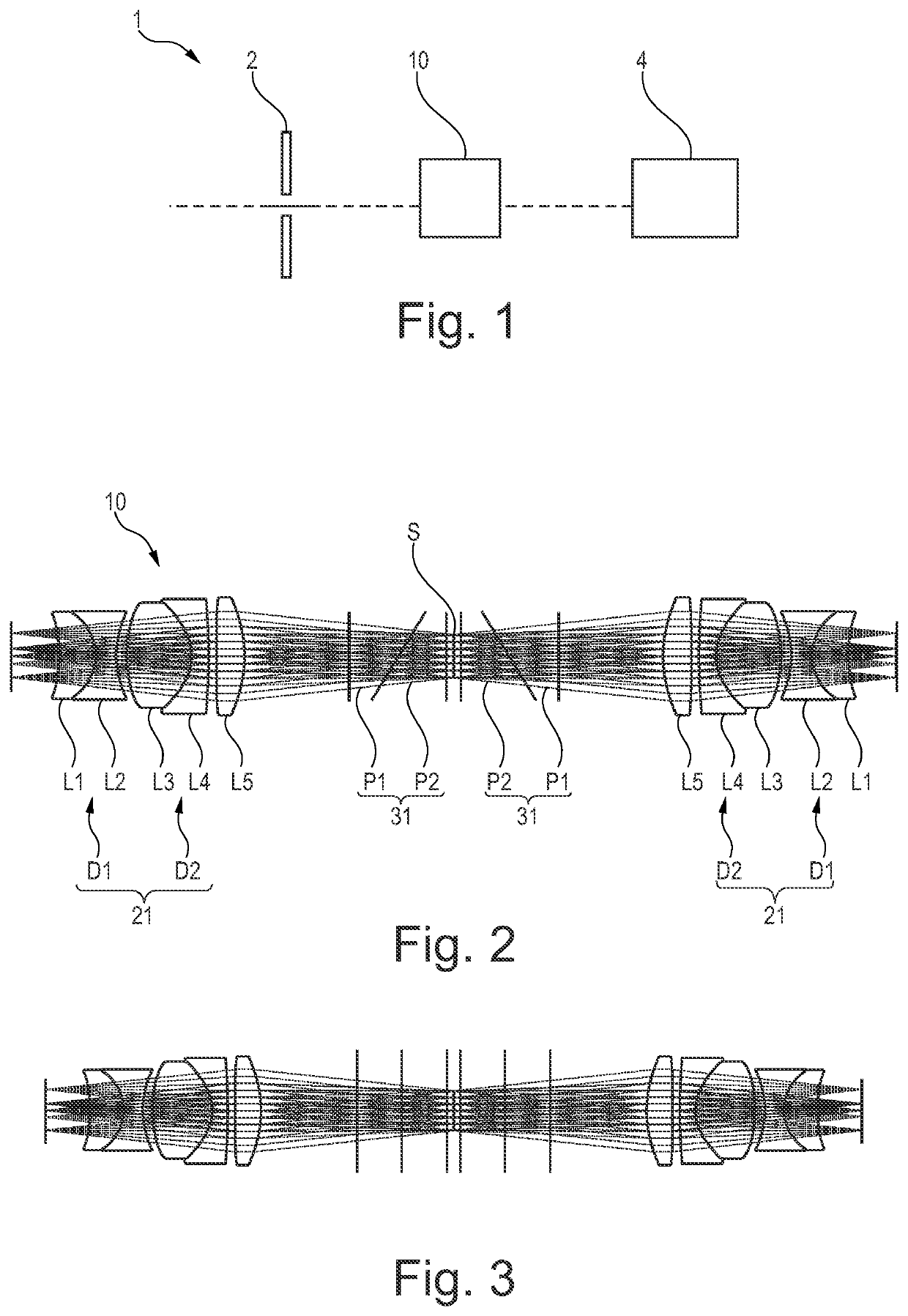
[0044]FIG. 1 illustrates an imaging device 1 according to an embodiment.

[0045]The imaging device 1 may be a hyperspectral imaging device, with a coded aperture plate 2 forming an object to be relayed by an optical relay 10 to an image at a detector 4.

[0046]The optical relay 10 is adapted to spectrally shear the image in one orientation across the detector, said detector having a suitably wide spectral response to all the sheared wavelengths.

[0047]The optical relay is an optical spectral shearing system and is illustrated in FIGS. 2 and 3.

[0048]FIG. 2 illustrates the optical spectral shearing relay system 10, in a plane of spectral shearing and FIG. 3 illustrates the optical spectral shearing relay system 10, in a plane of no spectral shearing, according to an embodiment of the invention, respectively

[0049]The optical spectral shearing relay system 10 of FIGS. 2 and 3 comprises a plurality of compound prisms 31 and a plurality of rotationally symmetric lens elements L1, L2, L3, L4, a...


PUM


Abstract

A spectrally shearing optical relay system, said relay system being comprised of two halves disposed symmetrically about an aperture stop S, wherein each half comprises a plurality of rotationally symmetric optical elements forming an objective and a com-pound prism comprised of a plurality of dispersing prisms. The compound prisms are located between the objectives and the aperture stop. An imaging device with such an optical relay system is also proposed.

Description

BACKGROUND OF THE INVENTIONField of the Invention[0001]The present invention relates to an optical relay system.Brief Description of the Related Art[0002]Coded aperture snapshot spectral imager (CASSI) is a computational imaging system that acquires a three-dimensional (3D) spectral data cube by single or a few two-dimensional (2D) measurements.[0003]A typical overall optical architecture comprises an imaging lens which images a scene onto a mask, a relay optical system comprising a dispersive element which relays the masked image through a dispersive element, and a sensor to detect the masked and sheared image. The original data cube is algorithmically reconstructed from the sensor input.[0004]The use of relay lenses and dispersing prisms in CASSI instruments is well known. The dispersive element may be a compound prism. The ‘pixels’ on the mask are matched to the pixels (or a 2×2 bin) of the sensor. Using a regular prism would result in undesirable optical effects such as anamorph...

Claims


Application Information

Patent Timeline
16 Jun 2022
Publication
US20220187511A1
IPC
G02B5/04; G02B27/00; G02B13/22
CPC
G02B5/04; G02B13/22; G02B27/0025; G01J2003/2826; G02B27/0062; G01J3/2823; G01J3/14; G02B9/10
Inventors
WANG, ROBIN; CHAPPELL, STEPHEN