Method and System for Controlling X-Ray Focal Spot Characteristics for Tomoysythesis and Mammography Imaging

a technology of tomoysythesis and focal spot characteristics, applied in the field of three-dimensional imaging technology, can solve the problems of image blurring and reduce diagnostic accuracy, and achieve the effects of reducing exposure, improving image clarity, and reducing blurring of tomosynthesis images

Active Publication Date: 2010-12-02
HOLOGIC INC
View PDF40 Cites 34 Cited by
  • Summary
  • Abstract
  • Description
  • Claims
  • Application Information

AI Technical Summary

Benefits of technology

[0002]Reconstructed tomosynthesis slices reduce or eliminate the problems caused by tissue overlap and structure noise in single slice two-dimensional mammography imaging. Digital breast tomosynthesis also offers the possibility of reduced breast compression, improved diagnostic and screening accuracy, fewer recalls, and 3D lesion localization.
[0003]Digital tomosynthesis combines digital image capture and processing with simple tube / detector motion as used in computed tomography (CT), however over a smaller rotational angle than that used in CT. Breast tomosynthesis systems are similar to mammography systems, with a distinct difference being that the x-ray source is moved to a variety of different imaging positions during tomosynthesis image acquisition.
[0005]In a conventional x-ray tube the focal spot is static relative to the tube, and since during each exposure period the x-ray source is continuously moved through space the focal spot is moving as well. The resultant focal spot movement causes image blurring and reduces diagnostic accuracy. It would be desirable to identify a mechanism for reducing undesirable image artifacts that result from x-ray source movement during a tomosynthesis or other image scan.SUMMARY OF THE INVENTION
[0006]According to one aspect of the invention, an improved x-ray tube is provided with the capability of modifying a focal spot characteristic to improve image clarity in a tomosynthesis system. The focal spot characteristics are modified by a combination of one or more approaches which include moving the static focal spot during a tomosynthesis exposure and / or changing a size of the static focal spot for tomosynthesis exposures. In one embodiment, a focal spot is moved during a tomosynthesis exposure period in a direction which opposes a directional movement of the x-ray tube through space such that an effective focal spot remains in substantially the same position during the entire tomosynthesis exposure. Such focal spot movement may be achieved by altering a position of a target on an anode or other methods. With such an arrangement a blurring of tomosynthesis images is reduced.
[0007]According to another embodiment, focal spot size may be varied in accordance with a type of imaging that is performed, such that a different focal spot size is used to obtain a mammogram or a tomosynthesis image. Alternatively a different focal spot size may be selected based on breast density. Focal spot size may be varied in accordance with an exposure period, with larger focal spots in general having smaller exposure periods. The ability to use a larger focal spot during tomosynthesis images, with a reduced exposure, allows the tomosynthesis scan speed to be increased while fully utilizing the x-ray tube capabilities. The ability to vary focal spot size enables full utilization of x-ray tube capabilities without sacrificing image quality for different imaging modes.

Problems solved by technology

In the interest of efficiency and image quality it is undesirable to stop the x-ray source at each imaging location, since such stop-and-start scanning procedures have been shown to reduce image quality.
The resultant focal spot movement causes image blurring and reduces diagnostic accuracy.

Method used


Image

  • Method and System for Controlling X-Ray Focal Spot Characteristics for Tomoysythesis and Mammography Imaging
  • Method and System for Controlling X-Ray Focal Spot Characteristics for Tomoysythesis and Mammography Imaging
  • Method and System for Controlling X-Ray Focal Spot Characteristics for Tomoysythesis and Mammography Imaging

Examples


Embodiment Construction

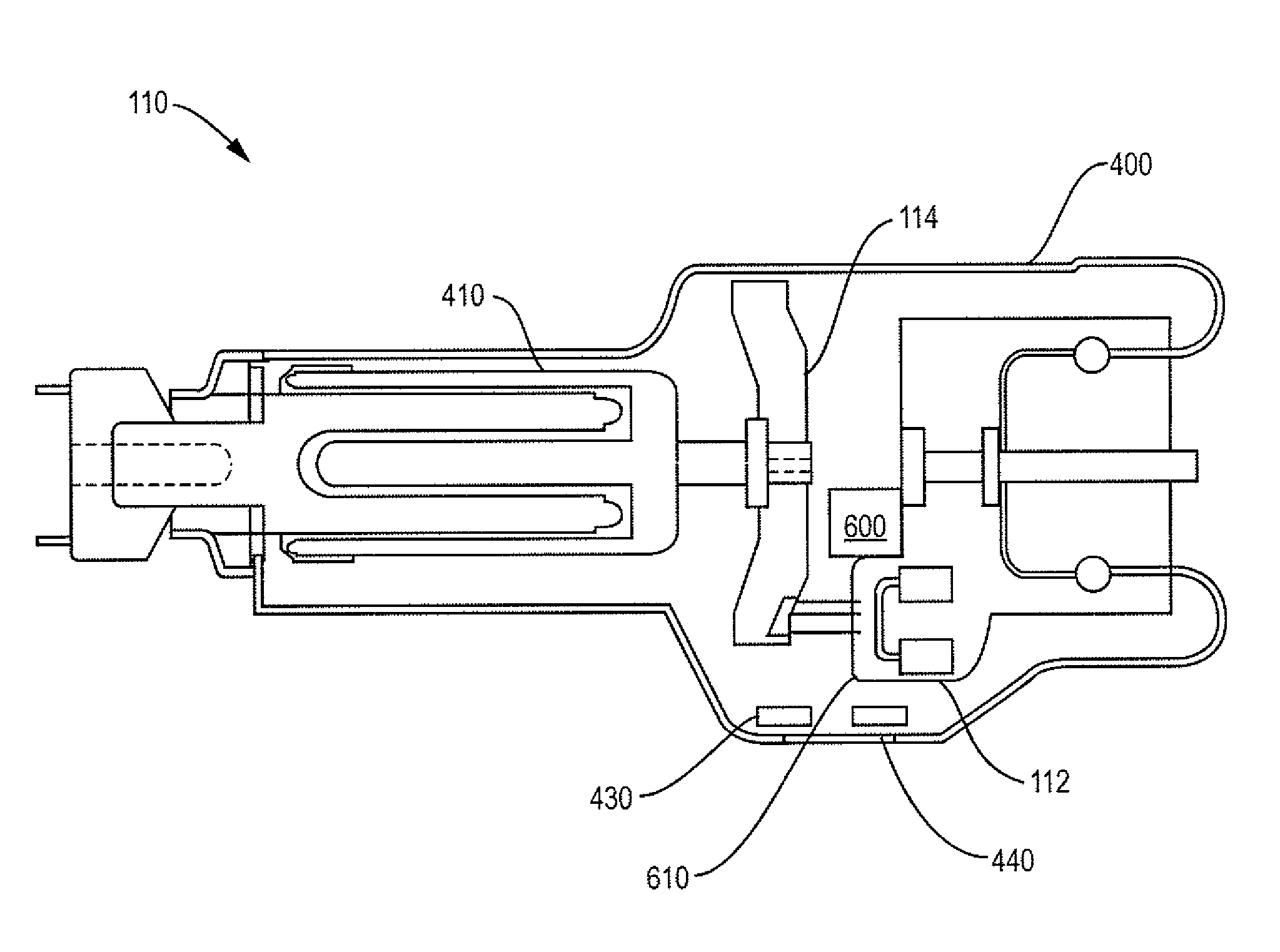
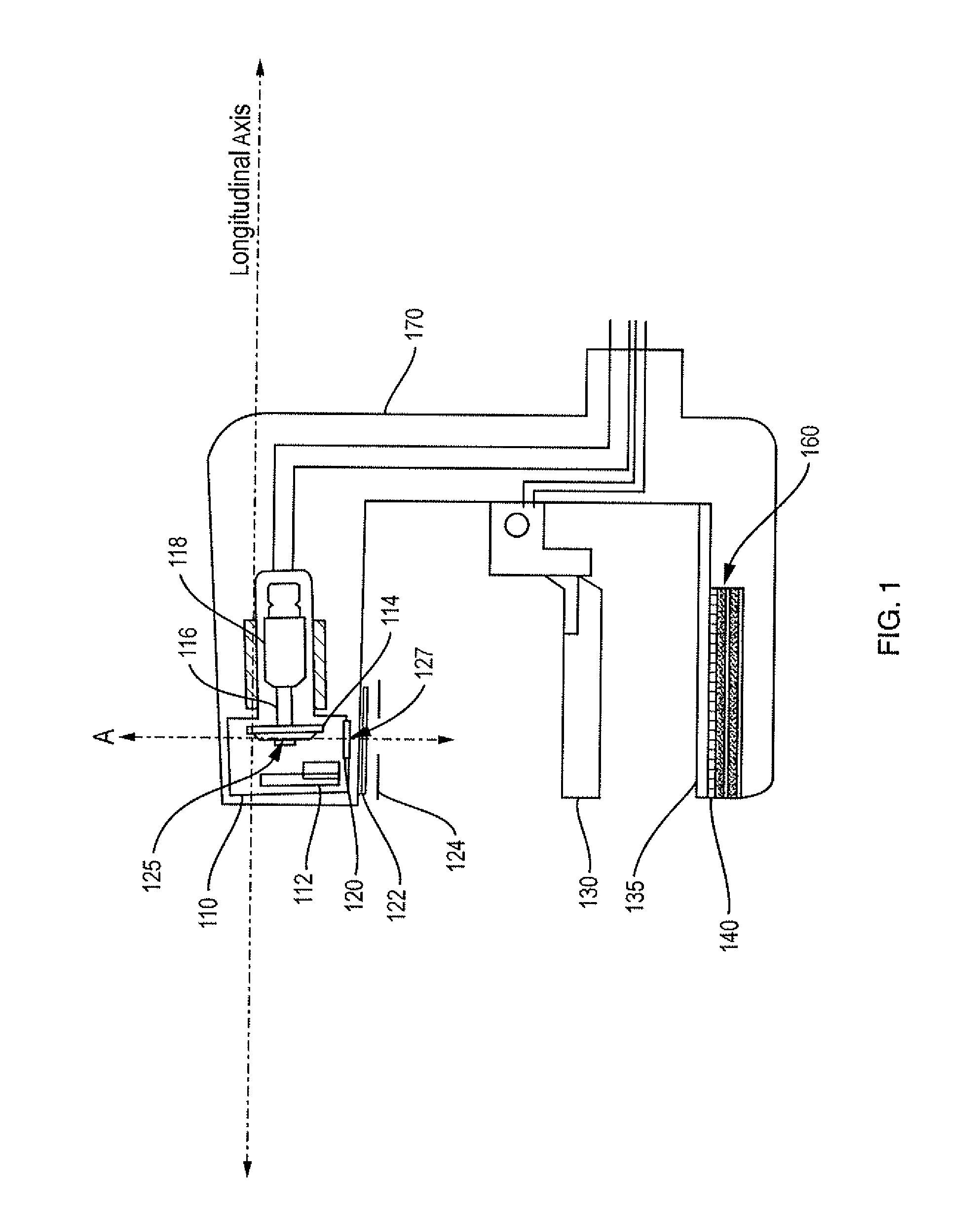
[0017]FIG. 1 illustrates a tomosynthesis system 100 which includes an x-ray tube 110, upper and lower compression paddles 130, 135, an anti-scatter grid 140 and a detector 160. The x-ray tube 110 includes a cathode 112, an anode 114 that is mounted on a shaft 116 and rotated by a motor 118, a tube port 120. Also shown attached to the x-ray tube are a filter 122 and a collimator 124.

[0018]The x-ray tube is a glass vacuum tube. Within the cathode 112 is a heated filament. When the x-ray tube is turned on, a current is passed through the filament, heating the filament and causing high energy electrons to be dislodged from the filament. A high voltage between cathode and anode causes the electrons to accelerate toward a target location 125 on the anode. The anode is made for example from tungsten and is rotated by motor 118 to avoid local overheating of the target location 125 on the anode.

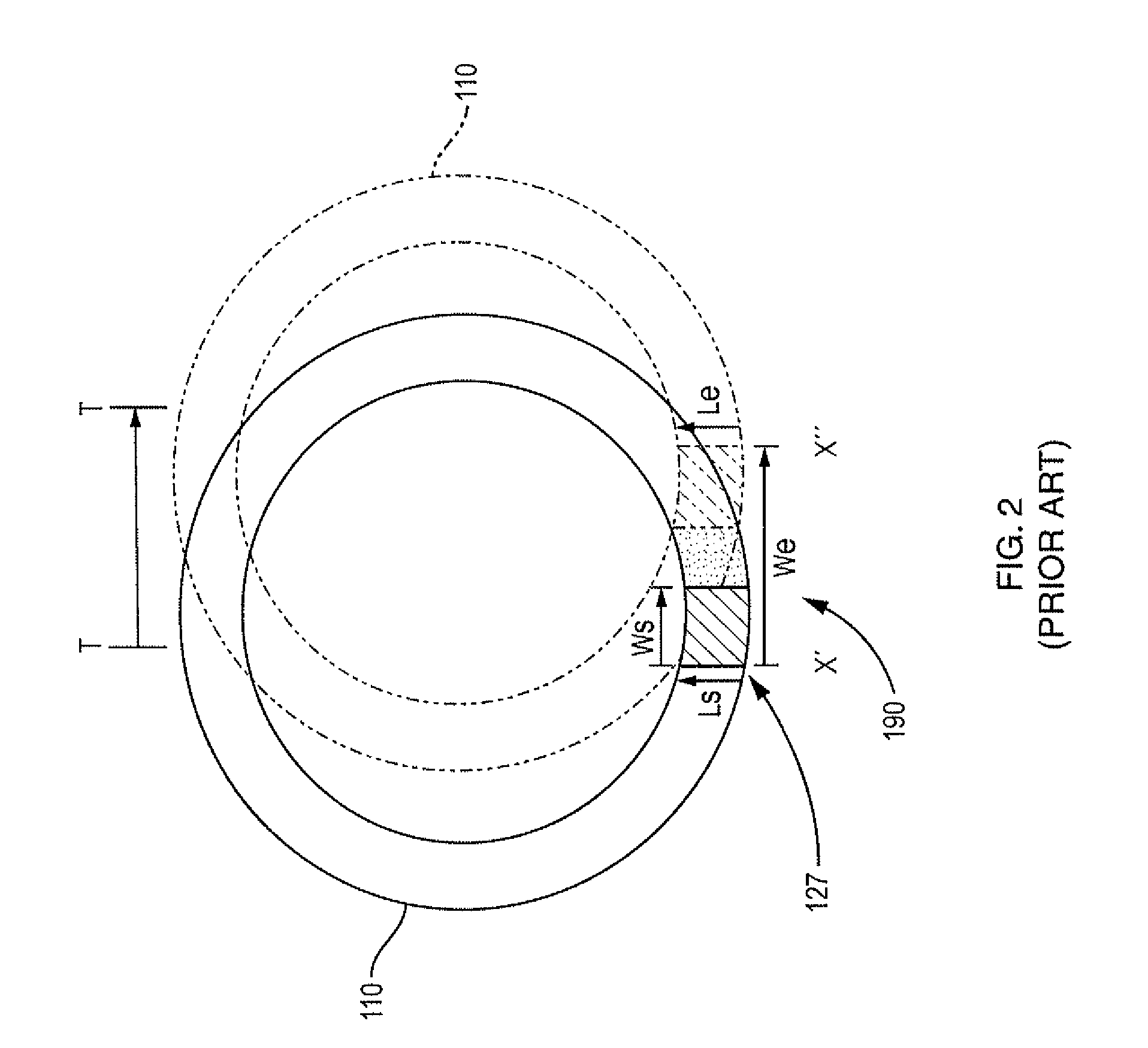
[0019]Electrons are focused to a specific target location by means of a focusing cup (not shown). ...


PUM

PropertyMeasurementUnit
exposure timeaaaaaaaaaa
widthaaaaaaaaaa
widthaaaaaaaaaa

Abstract

An x-ray tube is described that includes components for increasing x-ray image clarity in the presence of a moving x-ray source by modifying focal spot characteristics, including focal spot size and focal spot position. In a first arrangement a static focal spot is moved in a direction contrary to the movement of the x-ray source so that an effective focal spot position is essentially fixed in space relative to one of the imaged object and / or detector during a tomosynthesis exposure. In a second arrangement, the size of the static focal spot is increased, and the resulting increase in tube current reduces the exposure time and concomitant blur effect. The methods may be used alone or in combination; for example an x-ray tube with a larger, moveable static focal spot will result in a system that fully utilizes the x-ray tube generator, provides a high quality image with reduced blur and, due to the decrease in exposure time, may scan the patient more quickly.

Description

[0001]Breast tomosynthesis is a three-dimensional imaging technology that involves acquiring images of a stationary compressed breast at multiple angles during a short scan. The individual images are then reconstructed into a series of thin high-resolution slices that can be displayed individually or in a dynamic cine mode.[0002]Reconstructed tomosynthesis slices reduce or eliminate the problems caused by tissue overlap and structure noise in single slice two-dimensional mammography imaging. Digital breast tomosynthesis also offers the possibility of reduced breast compression, improved diagnostic and screening accuracy, fewer recalls, and 3D lesion localization.[0003]Digital tomosynthesis combines digital image capture and processing with simple tube / detector motion as used in computed tomography (CT), however over a smaller rotational angle than that used in CT. Breast tomosynthesis systems are similar to mammography systems, with a distinct difference being that the x-ray source ...

Claims


Application Information

Patent Timeline
Patent Type & Authority Applications(United States)
IPC IPC(8): G01N23/04H05G1/52
CPCA61B6/025A61B6/032A61B6/4021H01J35/14H05G1/52A61B6/502H01J35/147A61B6/03H01J35/24
Inventor REN, BAORUISTEIN, JAYJING, ZHENXUESMITH, ANDREW
Owner HOLOGIC INC
Why Eureka
Try Eureka