Conversion of infrastructure model geometry to a tile format

Active Publication Date: 2020-04-16
BENTLEY SYST INC
View PDF0 Cites 9 Cited by
  • Summary
  • Abstract
  • Description
  • Claims
  • Application Information

AI Technical Summary

Benefits of technology

[0008]Techniques are provided for converting geometry of an infrastructure model (e.g., an iModel® model), represented as high-level geometric primitives (e.g., b-splines, curves, cones, polyfaces, etc.) having a given symbology (e.g., color, line width, material etc.) to low-level primitives (e.g., meshes and polylines), and encoding these low-level primitives into tile contents (e.g., a binary representation) suited for transmission, and ultimately display upon, on a client device. Such techniques may address shortcoming of prior techniques. An architectural split between frontend applications and backend applications may allow conversion of the high level primitives to be performed remote from the client devices by backend applications. Backend applications may be executed on robust hardware devices that execute software in a multi-thread

Problems solved by technology

In the past, infrastructure models maintained according to such formats have been disjointed, and have included substantial data redundancies and other sources of inefficiency.
However, it has also lead to technical challenges.
One of these challenges involves how to efficiently display a view of an infrastructure model on a client device.
Since client devices may lack processing and storage capabilities for generating views themselves, they may instead rely upon cloud computing devices to “publish” the model.
While there are certain existing techniques for converting geometry of some types of infrastructure models to a form that can be readily displayed on a display screen of a client device, su

Method used


Image

  • Conversion of infrastructure model geometry to a tile format
  • Conversion of infrastructure model geometry to a tile format
  • Conversion of infrastructure model geometry to a tile format

Examples


Embodiment Construction

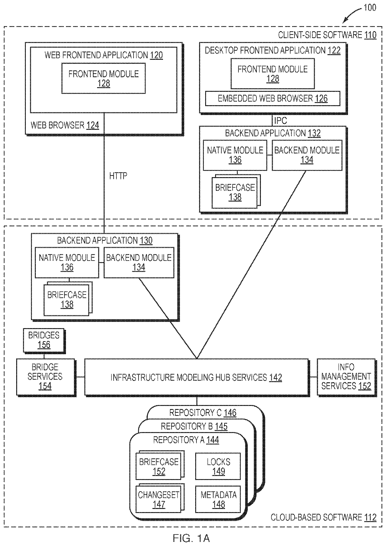
[0020]FIG. 1A is a high-level block diagram of an example infrastructure modeling software architecture 100. The architecture may be divided into client-side software 110 that executes on one or more computing devices provided local to an end-user (collectively “client devices”) and a cloud-based software 112 that is executed on one or more computing devices provided remote from the end-user (collectively “cloud computing devices”), accessible via a network (e.g., the Internet). The client-side software 110 may include web frontend applications 120 that operate within a virtual environment (e.g., a “browser sandbox”) provided by a web browser 124 (e.g., the Chrome® web browser), and desktop front-end applications 122 that operate directly under an operating system, and backend applications 132 that interact therewith. The cloud-based software 112 may include infrastructure modeling hub services (e.g., iModelHub™ services) 142, other services software 152, 154 and backend application...


PUM


Abstract

In example embodiments, techniques are provided for converting geometry of an infrastructure model represented as high-level geometric primitives having a given symbology to low-level primitives, and encoding these low-level primitives into tile contents suited for transmission, and ultimately display upon, on a client device. An architectural split between frontend applications and backend applications may allow conversion of the high level primitives to be performed remote from the client devices by backend applications. Backend applications may be executed on robust hardware devices that execute software in a multi-threaded environment on powerful CPUs. By performing CPU-intensive operations on backend applications, frontend applications on client devices may be required to do little more than submit low-level primitives for rendering on their GPU.

Description

RELATED APPLICATIONS[0001]Priority is claimed to previously filed U.S. Provisional Patent Application No. 62 / 745,375 filed on Oct. 14, 2018 for CONVERSION OF INFRASTRUCTURE MODEL GEOMETRY TO A TILE FORMAT by Connelly et al., the contents of which are incorporated herein by reference in their entirety.BACKGROUNDTechnical Field[0002]The present disclosure relates generally to infrastructure modeling, and more specifically to the display of views of infrastructure models utilizing tiles.Background Information[0003]Throughout the design, construction and operation of infrastructure (e.g., buildings, factories, roads, railways, bridges, electrical and communications networks, etc.) it is often desirable to model the infrastructure using infrastructure modeling applications. Infrastructure modeling applications traditionally have used a variety of different technologies and data formats to maintain infrastructure descriptions for different phases of the project. In the past, infrastructur...

Claims


Application Information

Patent Timeline
IPC IPC(8): G06T9/00
CPCG06T2210/32G06T9/001G06T2210/36G06T17/005G06T19/20G06T2210/04G06T2210/08G06T2219/2024
Inventor CONNELLY, PAULBENTLEY, RAYMOND B.
Owner BENTLEY SYST INC
Why Eureka
Try Eureka