
Adjustable spot light position generation

a spot light and position generation technology, applied in the field of adjustable spot light position generation, can solve the problems of increasing the cost and form factor of motorized components, requiring regular maintenance, and noisy motorized components, and achieve the effect of cost-effectiveness

Active Publication Date: 2020-04-23
SIGNIFY HLDG BV
View PDF2 Cites 4 Cited by
  • Summary
  • Abstract
  • Description
  • Claims
  • Application Information

AI Technical Summary

Benefits of technology

The present invention aims to provide a cheaper lighting device that can create a regularly adjusted spotlight. The technical effect is to simplify the process and make it more cost-effective.

Problems solved by technology

A drawback of the inclusion of such motorized components in such a lighting device is that it increases its cost as well as its form factor.
Moreover, such motorized components are noisy, prone to failure and therefore require regular maintenance.
A drawback of this luminaire is its relative complexity owing to the dedicated optics for each LED and the need to mount each LED on a dome-shaped surface.
This increases the cost of the luminaire.

Method used


Image

  • Adjustable spot light position generation
  • Adjustable spot light position generation
  • Adjustable spot light position generation

Examples


Embodiment Construction

[0038]It should be understood that the Figures are merely schematic and are not drawn to scale. It should also be understood that the same reference numerals are used throughout the Figures to indicate the same or similar parts.

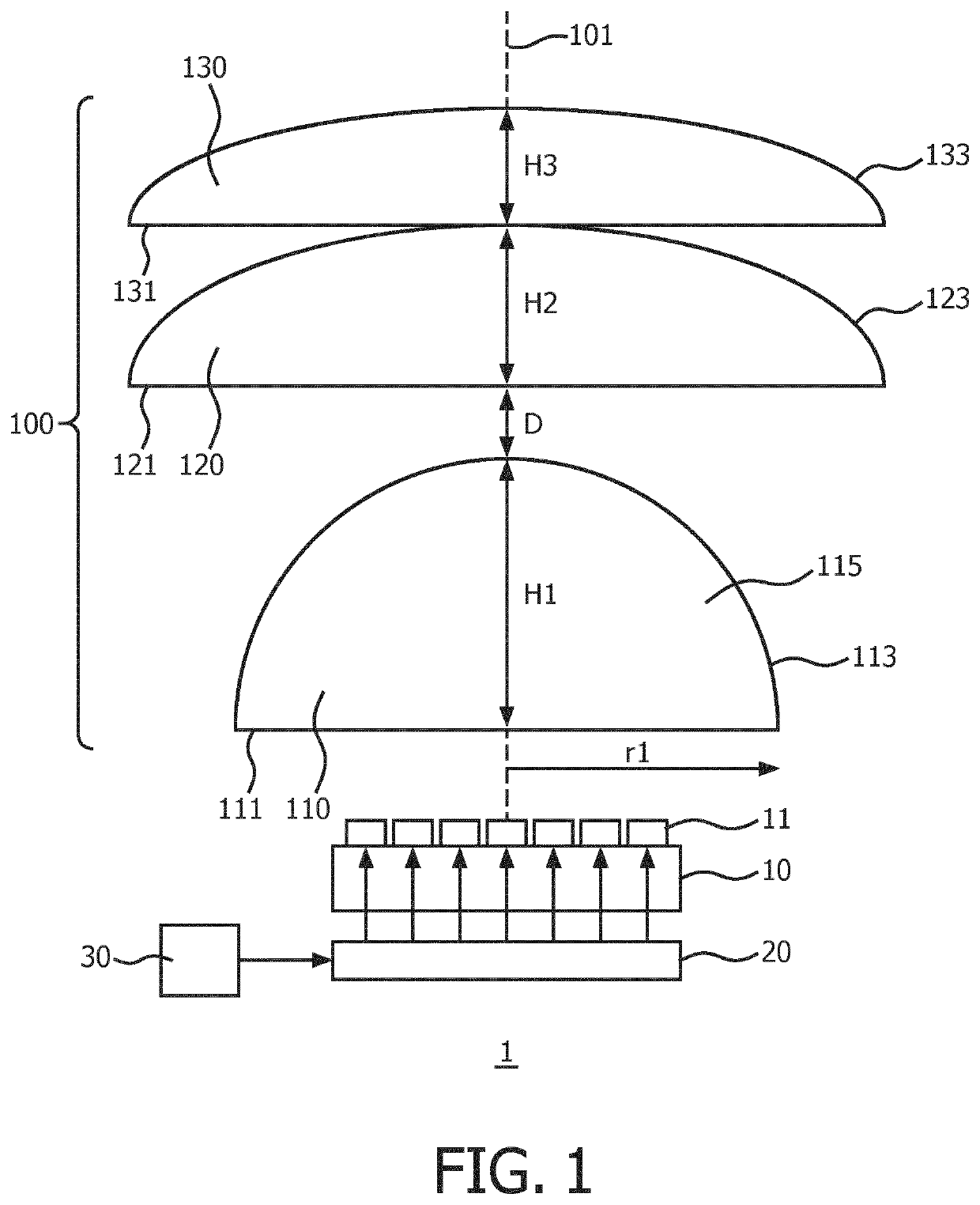
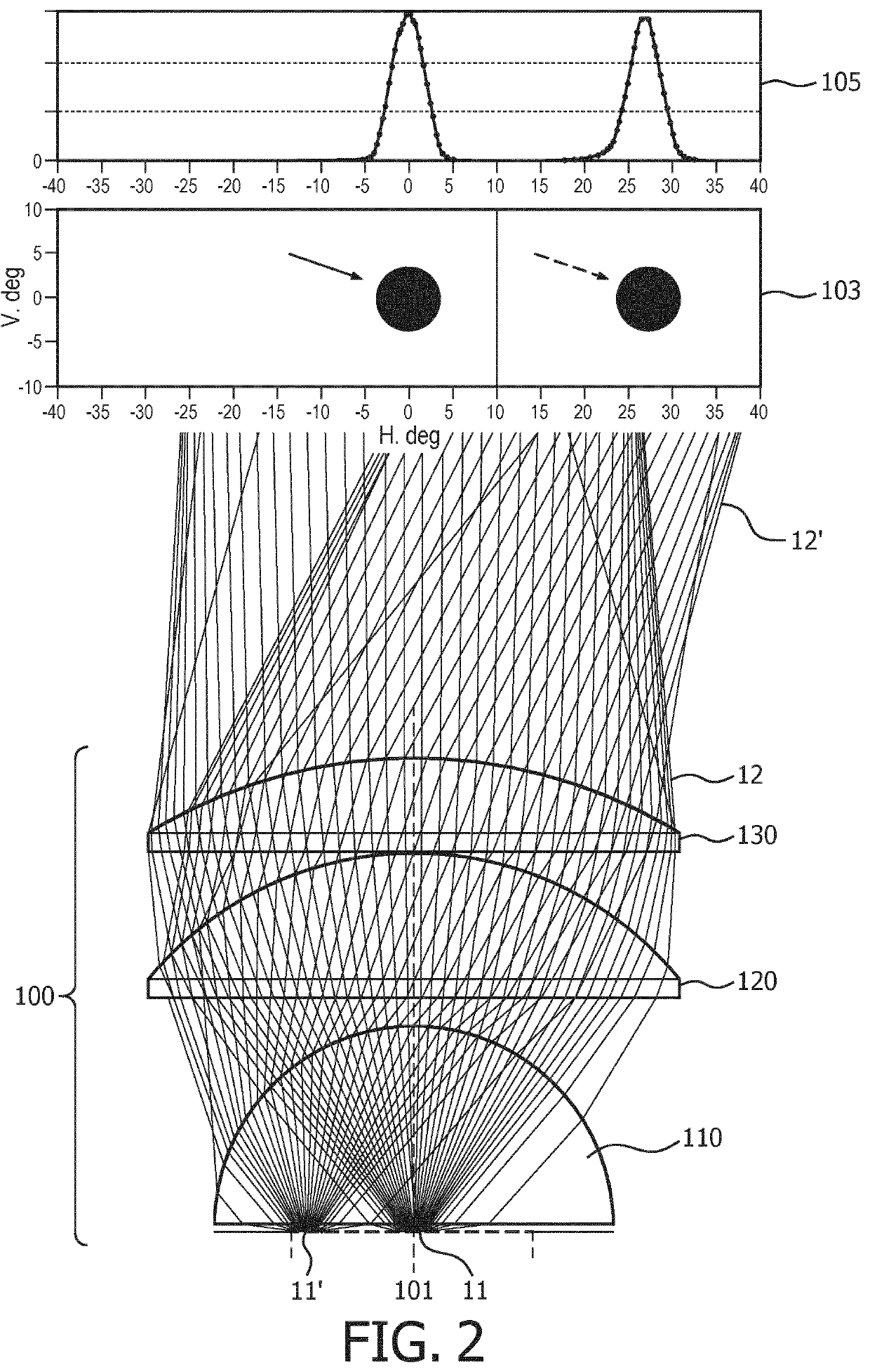
[0039]FIG. 1 schematically depicts a lighting device 1 according to an embodiment of the present invention. The lighting device 1 comprises a plurality of light sources 11 arranged in a planar array; in other words, each light source 11 is arranged to generate a luminous distribution along an optical axis, wherein the respective optical axes of the light sources 11 are aligned. In the context of the present application it should be understood that small deviations from a perfectly planar array are acceptable; for example, the array may be positioned on a slightly curved surface such that an angular spread of the angles between respective optical axes of the light sources 11 does not exceed 5°.

[0040]The light sources 11 preferably are solid-state light sources...


PUM


Abstract

Disclosed is a lighting device (1) for generating a dynamically adjustable spotlight without moving parts. The lighting device comprises a planar array of individually addressable sets of light sources (11), each set comprising at least one light source, each of said light sources being arranged to produce a luminous distribution; a controller (20) arranged to individually address said sets of light sources; and an optical system (100) 5 comprising a plurality of refractive lenses (110, 120, 130) common to the individually addressable light sources and arranged to shape the luminous distribution of each set of light sources into a spotlight (13) and project said spotlight in an angular direction that is a function of a position of said set in the array.

Description

FIELD OF THE INVENTION[0001]The present invention relates to a lighting device for generating a dynamically adjustable spotlight, such as a spotlight projector.BACKGROUND OF THE INVENTION[0002]In many application domains it is desirable to be able to remotely control the shape and / or projection location of a spotlight. Such application domains for example include retail applications, e.g. shops, entertainment applications, e.g. theatres, as well as domestic applications in which such spotlight control may increase the aesthetic appeal of a lighting application and / or increase the functionality of such a lighting application. To this end, the lighting device typically comprises a motorized component such as a motorized filter, motorized gobo wheels or other motorized optics, which motorized component is controlled to adjust the spotlight properties in a desired manner, e.g. a spotlight may be moved by controlling motorized gobo wheels accordingly. Similarly, the orientation of the li...

Claims


Application Information

Patent Timeline
Patent Type & Authority Applications(United States)
IPC IPC(8): F21V5/00G02B27/09
CPCF21W2131/406F21Y2115/10F21W2131/405F21V5/008G02B27/0922G02B27/0955F21S10/00F21V5/048F21Y2105/14F21V23/04
Inventor VAN GHELUWE, JOCHEN RENAATDROSS, OLIVERBERGMAN, ANTHONIE HENDRIK
Owner SIGNIFY HLDG BV
Learn More