
Cosmetic container

a container and cosmetic technology, applied in the field of cosmetic containers, can solve the problems of difficult control, difficult to completely use cosmetics, and difficult to determine the distance over which the piston has moved,

Inactive Publication Date: 2020-05-07
INTOPS +1
View PDF4 Cites 0 Cited by
  • Summary
  • Abstract
  • Description
  • Claims
  • Application Information

AI Technical Summary

Benefits of technology

The present invention aims to provide a cosmetic container with a dial that can be easily rotated to control the discharge of cosmetics. The invention includes a lifting and lowering guide portion and a through portion that prevent the piston arm from being rotated during dial rotation. The dial has first and second stepped portions that allow for easy placement and a guide groove and guide protrusion that prevent the dial from being rotated in reverse. The invention also utilizes elastic pieces and inclined surfaces to guide and prevent dial rotation. Overall, the invention enables more precise and easy control over makeup application.

Problems solved by technology

The tube- or pump-type containers are disadvantageous in that when a tube or pump is pressed or pushed to discharge cosmetics, it is difficult to perform control so that a desired quantity of cosmetics can be discharged and in that it is also difficult to completely use cosmetics because cosmetics remain in a container.
However, the rotational discharge-type cosmetic containers are also disadvantageous in that when a user performs rotational manipulation, it is difficult to determine the distance over which the piston has moved, and thus it is difficult to perform control so that a desired quantity of cosmetics can be discharged.
Accordingly, the rotational discharge-type cosmetic containers are disadvantageous in that it is inconvenient to use cosmetics while holding a hand mirror with one hand.

Method used


Image

  • Cosmetic container
  • Cosmetic container
  • Cosmetic container

Examples


Embodiment Construction

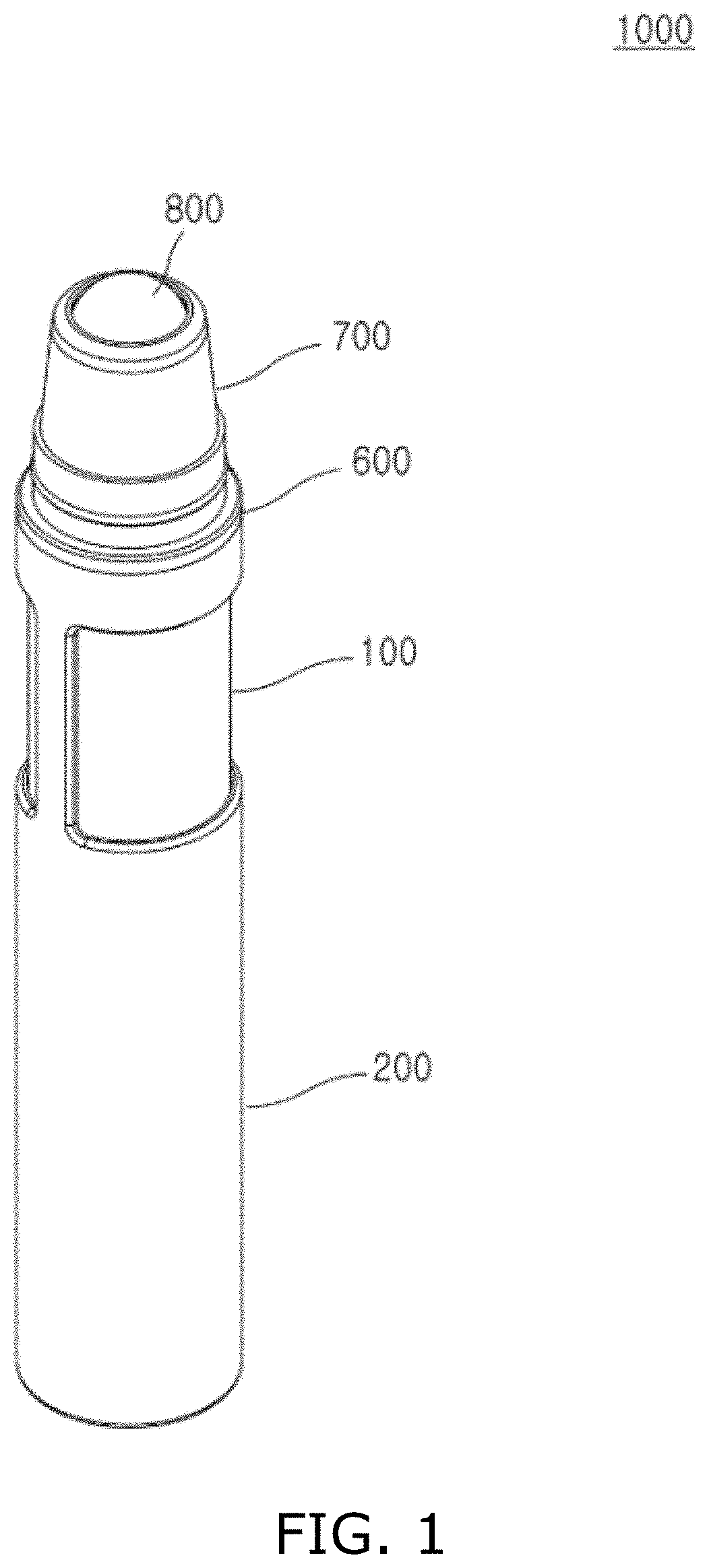
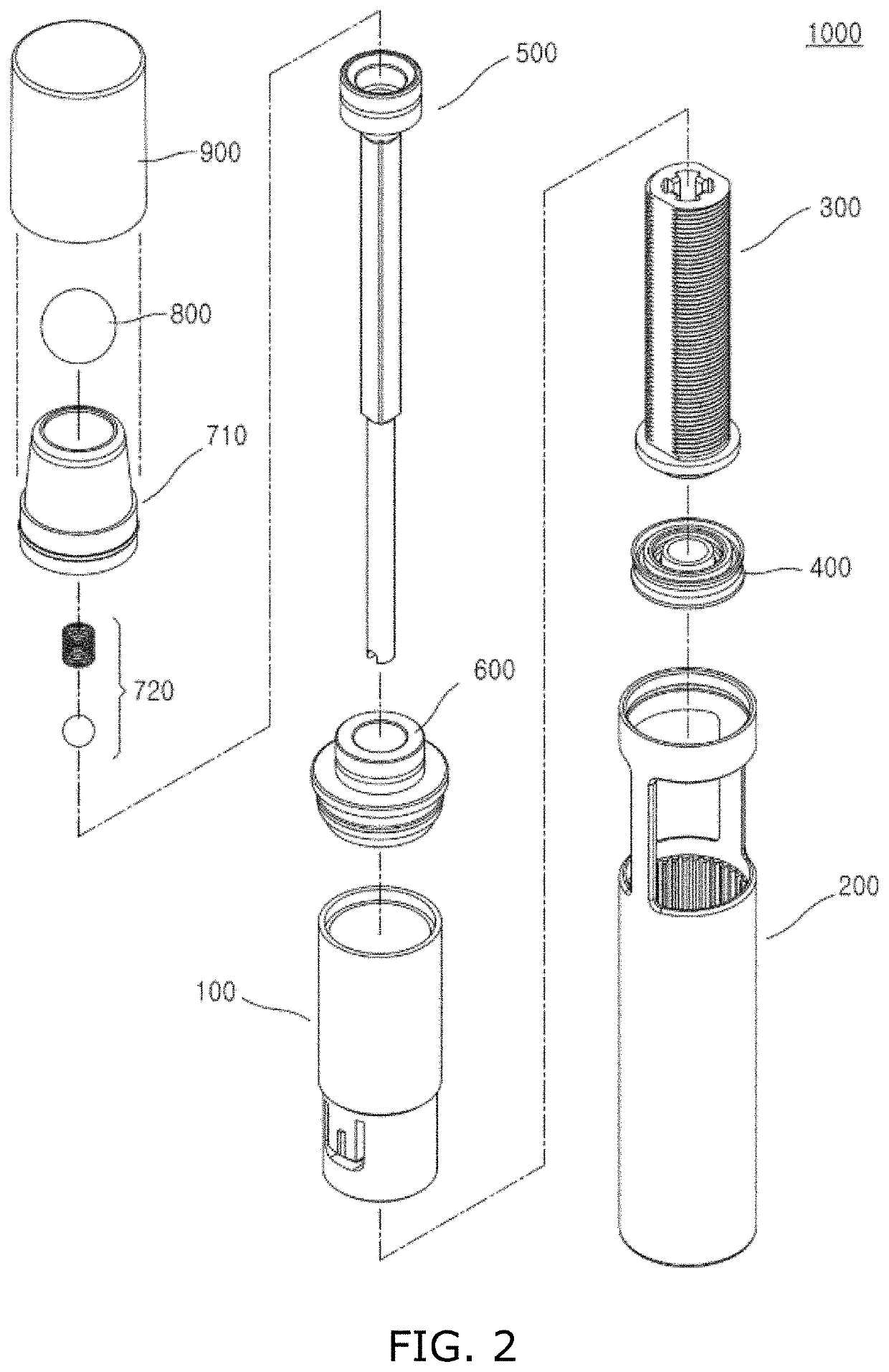
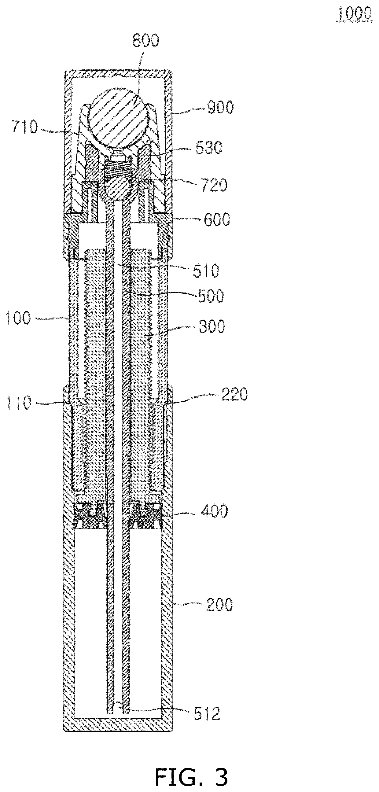
[0035]Embodiments of the present invention will be described in detail below with reference to the accompanying drawings. It should be noted that when reference symbols are assigned to components, the same reference symbols will be assigned to the same components as much as possible even when the components are shown in different drawings. Furthermore, in the following description of the embodiments of the present invention, when it is determined that a detailed description of a related well-known configuration or function disturbs the understanding an embodiment of the present invention, the detailed description will be omitted. Furthermore, although the embodiments of the present invention will be described below, the technical spirit of the present invention is not limited to the embodiments, various modifications may be made by those skilled in the art, and the present invention may be practiced in various forms. Meanwhile, upward, downward, left, and right directions are based ...


PUM


Abstract

Disclosed herein is a cosmetic container. The cosmetic container includes: a dial configured to receive rotating force; a container part configured such that cosmetics are accommodated in the lower side thereof and the dial is relatively rotatably disposed in the upper side thereof; a piston arm disposed inside the container part, and configured to be selectively lifted and lowered by the rotation of the dial; a piston disposed to come into tight contact with the inner wall of the container part, and configured to be coupled to the lower portion of the piston arm and to be selectively lifted and lowered; and a transfer tube disposed inside the container part, and configured such that a transfer flow path is formed therein; wherein when the piston arm and the piston are lowered and press the cosmetics, the cosmetics enter into the lower portion of the transfer tube and are discharged.

Description

CROSS-REFERENCE TO RELATED APPLICATION[0001]This application claims the benefit of Korean Patent Application No. 10-2018-0133238 filed on Nov. 2, 2018, which is hereby incorporated by reference herein in its entirety.BACKGROUND1. Technical Field[0002]The present invention relates generally to a cosmetic container, and more specifically to a cosmetic container that enables the discharge of cosmetics to be more easily controlled through the rotation of a dial.2. Description of the Related Art[0003]Generally, cosmetics are basically classified into solid, powder, and liquid forms. Various containers are used depending on the form of cosmetics. In recent years, cosmetics, such as foundations and lipsticks, have been supplied in a gel or liquid form, rather than a powder or solid form. Conventionally, tube- and pump-type containers have been widely used to accommodate such liquid cosmetics.[0004]The tube- or pump-type containers are disadvantageous in that when a tube or pump is pressed ...

Claims


Application Information

Patent Timeline
Patent Type & Authority Applications(United States)
IPC IPC(8): A45D34/04
CPCA45D2040/208A45D34/041A45D34/00A45D2034/002A45D2200/056A45D40/20A45D40/261A45D2200/055B65D47/42B65D83/0011B65D2203/12
Inventor KIM, KEUN HACHOI, JUNG AHJOO, JIN HOLEE, EUNAH
Owner INTOPS
Learn More