Connector for precast concrete structures

a technology of precast concrete and connectors, which is applied in the direction of construction, building components, construction materials, etc., can solve the problems of similar difficulty in assembly, unnecessary time and cost associated with assembling precast panels and/or floor joists, etc., and achieves the effect of reducing the portion of the connector system that is exposed, reducing the likelihood of tampering, and increasing the head heigh

Active Publication Date: 2020-05-07
MEADOW BURKE
View PDF0 Cites 2 Cited by
  • Summary
  • Abstract
  • Description
  • Claims
  • Application Information

AI Technical Summary

Benefits of technology

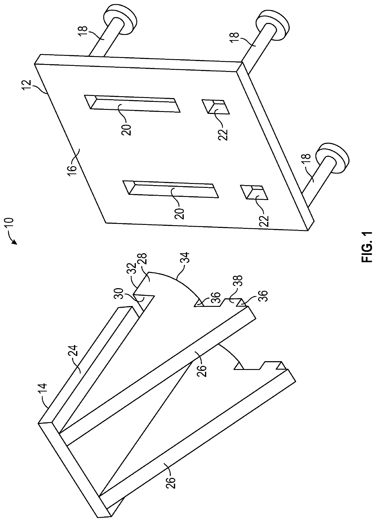
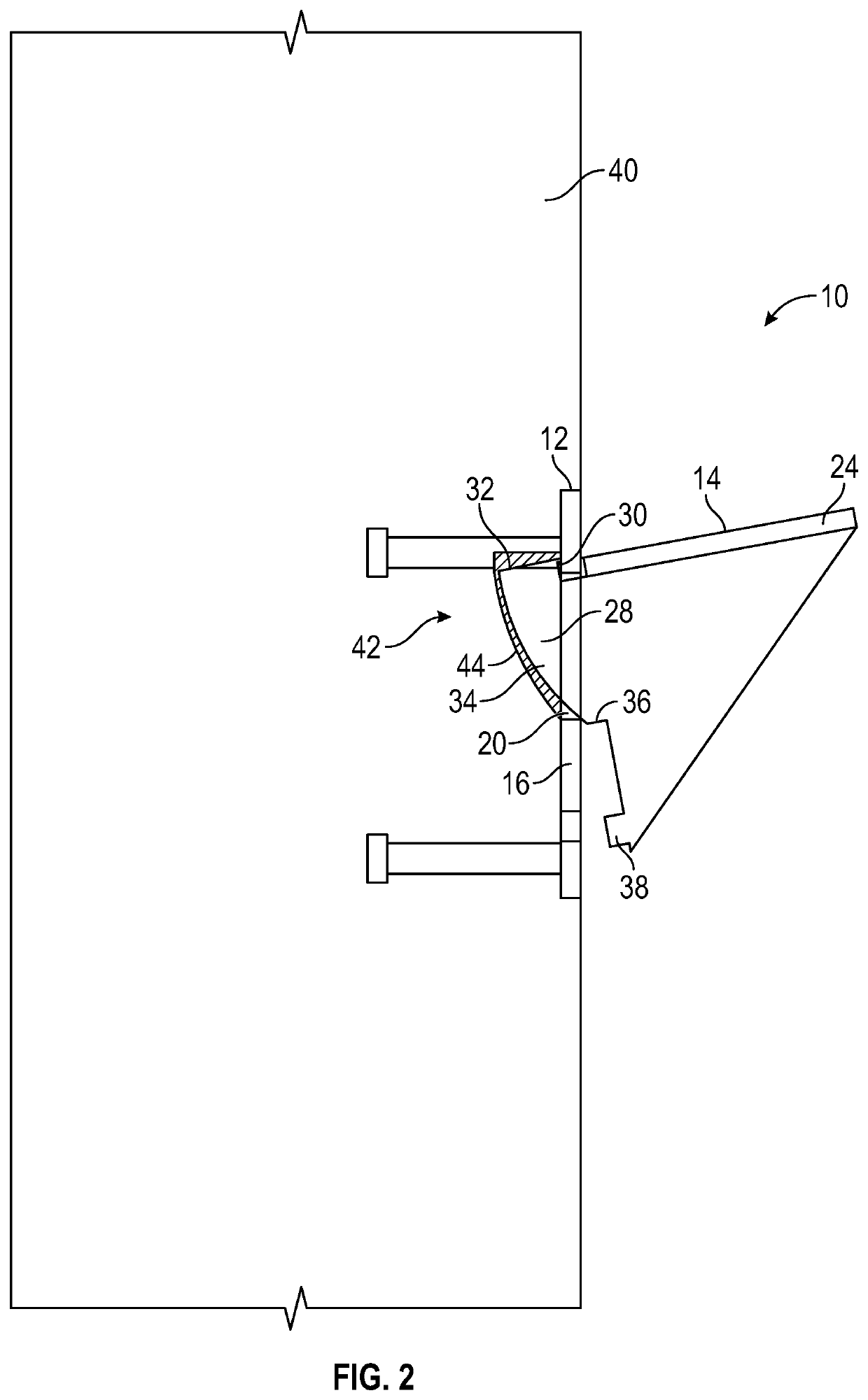
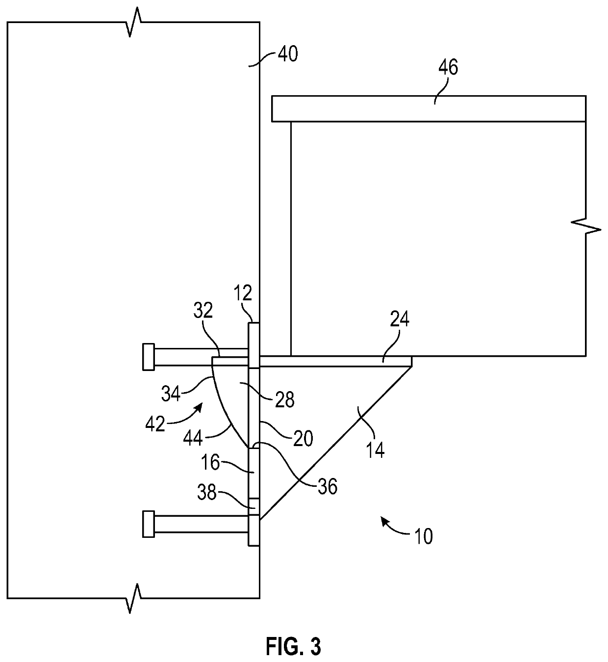
[0007]A further aspect of the present invention is to provide a connector system with an attachment member that has an arcuate surface which facilitates rotation of the attachment member into the receiving member. The retention surface of a protrusion of the attachment member must extend above the aperture in the receiving member, and to do so, the distance between a distal end of the retention surface and the bearing surface of the attachment member is larger than the longitudinal distance of the aperture in the receiving member. Stated another way, the distance between a top surface that is adjacent the retention surface and the bearing surface is larger than the longitudinal distance of the aperture. Thus, in a first position, the attachment member and associated surfaces are oriented at an acute angle relative to the receiving member so that the retention surface of the protrusion can pass through the aperture of the receiving member. As the attachment member is inserted into the aperture of the receiving member, an arcuate surface of the attachment member contacts an arcuate surface defined by a void former. The arcuate void in the precast concrete wall panel allows the attachment member to rotate into a second position such that the acute angle is reduced to substantially zero degrees, the retention surface of the attachment member is positioned against a back surface of the receiving member, and the bearing surface of the attachment member is seated on an inner surface of the aperture of the receiving member. It will be appreciated that other embodiments can have non-arcuate transition surfaces between a top surface and a bearing surface.
[0010]A further aspect of embodiments of the present invention is to provide an attachment member with a horizontal member located at a lower position on the attachment member. With the lower position, the horizontal member can position a second structural member that rests on the horizontal member lower with respect to the precast concrete panel that has the receiving member. This allows a second structural member to be positioned lower on sprandrel beams and closer to the top of openings in a parking garage application to increase head heights. This also minimizes the portion of the connector system that is exposed to reduce the likelihood of tampering, damage from an impact, etc. In addition, side plates can extend up from the horizontal member to provide lateral stability to a second structural member that is positioned on the horizontal member. This increase in stability improves the overall safety of the structure in which the connector system is used and can improve the survival of the structure in, for example, an earthquake.

Problems solved by technology

These references also describe connectors that use keyhole and hook combinations which can be similarly difficult to assemble.
Thus, unnecessary time and costs associated with assembling the precast panels and / or floor joists may occur, as well as inherent safety issues associated with positioning a large concrete structure.

Method used


Image

  • Connector for precast concrete structures
  • Connector for precast concrete structures
  • Connector for precast concrete structures

Examples


Embodiment Construction

[0040]The present invention has significant benefits across a broad spectrum of endeavors. It is the Applicant's intent that this specification and the claims appended hereto be accorded a breadth in keeping with the scope and spirit of the invention being disclosed despite what might appear to be limiting language imposed by the requirements of referring to the specific examples disclosed. To acquaint persons skilled in the pertinent arts most closely related to the present invention, a preferred embodiment that illustrates the best mode now contemplated for putting the invention into practice is described herein by, and with reference to, the annexed drawings that form a part of the specification. The exemplary embodiment is described in detail without attempting to describe all of the various forms and modifications in which the invention might be embodied. As such, the embodiments described herein are illustrative, and as will become apparent to those skilled in the arts, may be...


PUM


Abstract

An apparatus, system, and method is provided to connect precast concrete panels to a structural member. The connector can have a receiving member embedded in a precast concrete panel and can further have an attachment member that selectively interconnects to the receiving member. This attachment member can have a surface that is oriented substantially perpendicular to the precast concrete panel and that receives or supports a structural member such as a floor joist or a second precast concrete panel. The configuration of a protrusion of the attachment member allows for a rapid and secure interconnection with an aperture in the receiving member. A builder can use the connector system described herein to rapidly and securely assemble multiple precast concrete panels to structural members in the construction of, for example, a parking garage or other similar structure.

Description

CROSS-REFERENCE TO RELATED APPLICATIONS[0001]This application is a divisional of U.S. patent application Ser. No. 15 / 994,084 filed May 31, 2018, which claims priority under 35 U.S.C. § 119(e) to U.S. Provisional Patent Application Ser. No. 62 / 512,835 filed May 31, 2017, the disclosures of which are incorporated herein in their entireties by reference.FIELD OF THE INVENTION[0002]The present invention is directed to the assembly of precast concrete panels, and more specifically to connectors used to orient, position, and secure precast concrete panels and floor joists relative to each other.BACKGROUND OF THE INVENTION[0003]Precast concrete panels and associated connectors are widely used in the construction industry. Traditional concrete structures are formed in place and on site, whereas precast concrete panels are poured and cured off site in a modern manufacturing facility before being transported to the building site. Precast concrete panels allow for better quality control and re...

Claims


Application Information

Patent Timeline
Patent Type & Authority Applications(United States)
IPC IPC(8): E04B1/41E04B1/04E04B1/21
CPCE04B1/41E04B1/043E04B1/4114E04B1/215E04B2001/405E04B2103/06E04B5/06E04B2103/02E04B2001/389
Inventor KELLY, DAVIDRECKER, MICHAEL J.HARTMAN, GARYNAUMANN, RONALD G.FRANCIES, III, SIDNEY E.
Owner MEADOW BURKE
Why Eureka
Try Eureka