Elongated lighting module and lighting system

a technology of lighting modules and lighting systems, applied in the direction of fixed installation, lighting and heating equipment, lighting support devices, etc., can solve the problems of relative unpleasant lighting as provided by the known lighting system, the sharp light-dark contrast between the bright illuminated ceiling and the bulky, dark cover of the lighting system, etc., to achieve simple physical substitution, simple electrical connection, and simple installation of the elongated lighting modules

Active Publication Date: 2020-05-07
SIGNIFY HLDG BV
View PDF0 Cites 5 Cited by
  • Summary
  • Abstract
  • Description
  • Claims
  • Application Information

AI Technical Summary

Benefits of technology

[0043]The elongated lighting module may have the feature that electric control components are accommodated in the housing in a compartment located below the plurality of LEDs. Thus a compact elongated lighting module is obtained which holds all equipment for operation, and only needs to be electrically connected to mains, i.e. driver equipment needs not to be installed on the ceiling, thus simplifying installation of the elongated lighting modules.
[0044]The invention further relates to a lighting system comprising at least two mutually end-to-end coupled elongated lighting modules according to the invention lying in line with each other. Typically the number of end-to-end coupled elongated lighting modules that are in extension with each other may vary from a small number, for example two, three, or four, to a relatively large number, for example ten, twenty or even up to hundred. The typical length of a single elongated lighting module could be in the range of 30 cm to 360 cm, for example 60 cm or 120 cm. The end-to-end couple elongated lighting modules may have the feature that they are mutually both mechanically and electrically coupled. Such a way of end-to-end coupling enables i) simple physical substitution of a single elongated lighting module from a line of coupled elongated lighting modules in a direction transverse to said line and without the need for shifting / displacing adjacent elongated lighting modules in a direction along the line, and enables ii) a simple electrical connection and electrically driving / operating the elongated lighting modules with a single connector and / or driver for a plurality of elongated lighting modules.
[0045]The lighting system may have the feature that the elongated lighting modules are end-to-end coupled via a connection module, either inserted in between two adjacent elongated lighting modules or mounted on side surfaces, i.e. not the surfaces of adjacent elongated lighting modules that are facing each other, of abutting end portions of the adjacent elongated lighting modules. Such a connection module may have the feature that it comprises a sensor, for example a (day)light sensor, an occupation sensor, and IR-sensor, an alarming device, for example a sound horn, a flashlight, a sprinkler head, and / or it may have the feature that it comprises an additional light source, for example an additional LED providing direct illumination, for example emergency or spotlight illumination. The connection module may have the feature that it comprises on opposite ends respective end faces that are in mutually angled position in the plane P perpendicular to the suspension axis and / or parallel to the supporting structure. Connection between two adjacent elongated lighting modules is done via said end faces and then results in the elongated lighting modules to be oriented in a mutually angled position, for example at a mutual angle of 30°, 45° or 90° in said plane P. Thus even more freedom of positioning of the elongated lighting modules with respect to the ceiling grid structure is enabled.

Problems solved by technology

The relatively unpleasant lighting as provided by the known lighting system is caused by the bulky, reflective cover.
Said cover is used to capture and reflect light originating from the wide beam emitting light sources to the ceiling, but that at the same time causes sharp light-dark contrasts between the bright illuminated ceiling and the bulky, dark cover of the lighting system.

Method used


Image

  • Elongated lighting module and lighting system
  • Elongated lighting module and lighting system
  • Elongated lighting module and lighting system

Examples


Embodiment Construction

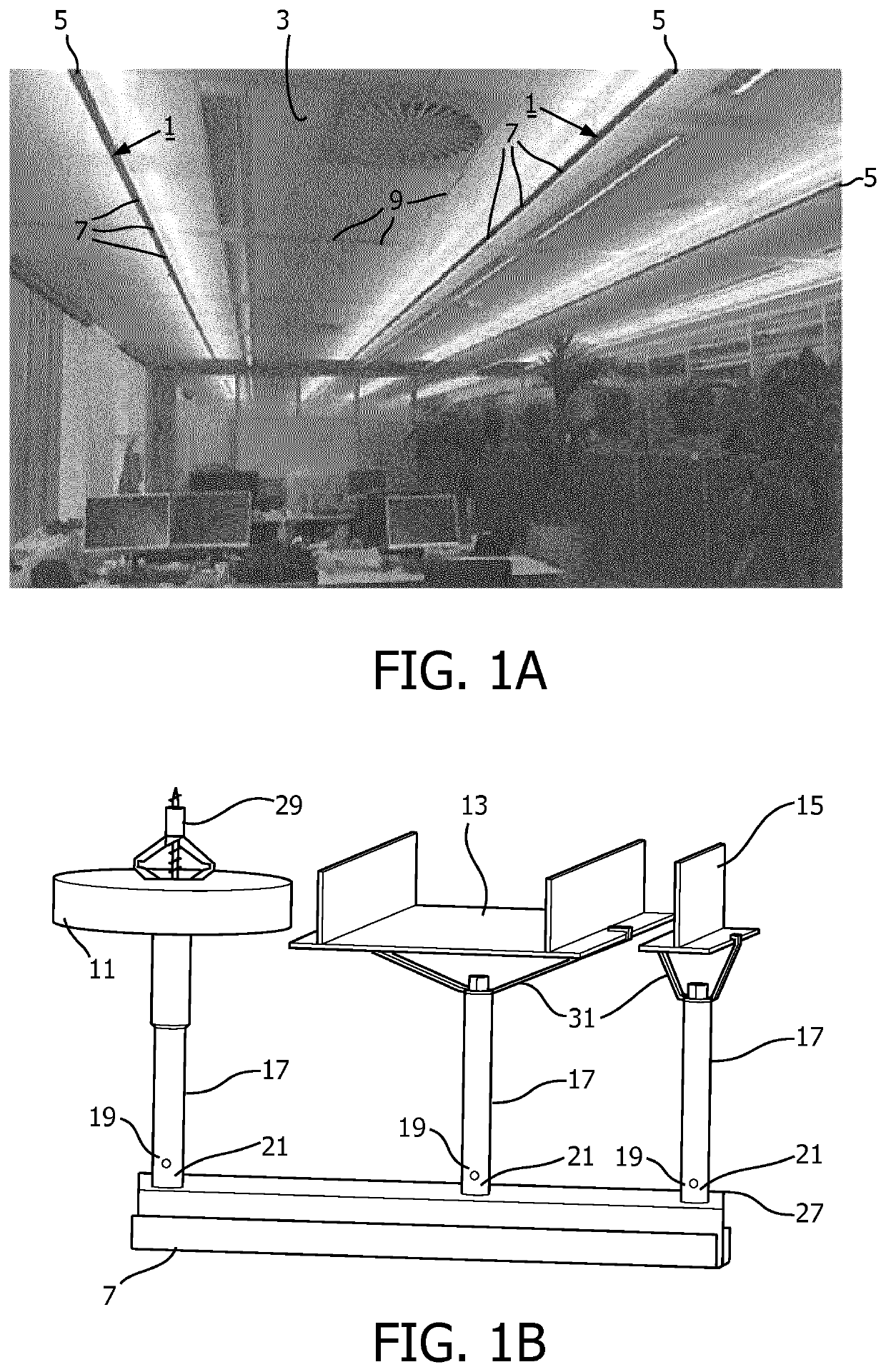
[0056]FIG. 1A shows a lighting system 1 according to the invention installed at a ceiling 3 of an office at a test location, in the figure an indirect lighting system. The lighting system comprises a plurality of parallel extending rows 5 of a plurality of end-to-end coupled elongated, indirect lighting modules 7. As shown the ceiling has grid structure 9 from which the rows of elongated lighting modules are suspended, said rows extend parallel to the grid structure. The lighting system issues light toward the ceiling which diffusely reflects said light and thus provides indirect, ambient light in the office. A comfortable illumination is attained in which glare is essentially absent as a direct view of light sources is counteracted by the configuration of the lighting system.

[0057]FIG. 1B shows various types of ceiling structures to which an elongated lighting module 7 is mounted. The ceiling structure can, for example, be a ceiling tile 11, a double T-bar 13 or a single T-bar 15 c...


PUM


Abstract

An elongated, indirect lighting module comprising a plurality of LEDs arranged along a longitudinal axis in a housing provided with a mounting element having an elongated shape in axial direction. The elongated lighting module further comprising suspension elements for suspended connection of the housing to a ceiling. Each suspension element has at a first end a first connector connected to the mounting element, and at a second, opposite end a second connector for connection to the ceiling. The suspension element via its first connector is displaceable along the longitudinal axis over the mounting element, and the LEDs are configured to issue light into a radial direction essentially away from both the mounting element and the suspension element and for a major part toward the ceiling.

Description

BACKGROUND OF THE INVENTION[0001]The invention relates to an elongated lighting module for providing general and / or ambient lighting, typically this attained in a convenient manner by an elongated, indirect lighting module. The invention further relates to a (n indirect) lighting system comprising at least two end-to-end coupled elongated lighting modules. A lighting module or lighting system having the features of an indirect lighting module / system provides essentially only indirect lighting and the issue of direct light is very limited, i.e. for example less than 10% of the total issued light. In a suspended indirect lighting module or system, light is not issued from the module / system directly downwards, i.e. in the direction of gravity, but essentially light is only provided to the ambient in a downward direction after first being directed upwardly towards a (false) ceiling and subsequently reflected therefrom in a downward direction. In analogy, the same applies for an indirect...

Claims


Application Information

Patent Timeline
Patent Type & Authority Applications(United States)
IPC IPC(8): F21S2/00F21S8/06F21V3/02F21V21/112F21V21/22F21V21/005F21V23/06
CPCF21V21/005F21V3/02F21V21/112F21S8/06F21Y2103/10F21V21/22F21S2/005F21V23/06F21Y2115/10F21V21/008F21V17/104F21V21/14
Inventor GIELEN, VINCENT STEFAN DAVIDVAN MONTFORT, VINCENT JOHANNES JACOBUSVISSENBERG, MICHEL CORNELIS JOSEPHUS MARIE
Owner SIGNIFY HLDG BV
Why Eureka
Try Eureka