
Monolithic broadband ultrasonic vibration isolation with small form factor

a technology of ultrasonic vibration isolation and monolithic broadband, which is applied in the manufacture of shock absorbers, springs/dampers, instruments, etc., can solve the problems of increasing production costs, reducing thermal conductivity, and lack of available modes, and achieves the effect of increasing the reliability of the band gap of the manufactured devi

Inactive Publication Date: 2020-05-14
UNIVERSITY OF VIENNA
View PDF0 Cites 9 Cited by
  • Summary
  • Abstract
  • Description
  • Claims
  • Application Information

AI Technical Summary

Benefits of technology

The patent text describes a way to make electronic devices more reliable. This is done by shaping the transition regions between bridges and resonant masses in a way that increases the band gap of the device.

Problems solved by technology

The lack of available modes prevents vibrations of frequencies within the bandgap to travel through the device.
Many of these systems only work in a specific orientation, i.e. since gravity needs to be taken into account for low frequencies, and these systems typically need alignment, which increases production costs.
In addition, these systems typically require large springs with small cross-sections, which reduce thermal conductivity.
While these systems may exhibit a rather small form factor, they are typically not monolithic and have lower thermal conductivity.
Furthermore, most elastomers would not be suitable for applications in vacuum systems, and none of them would be suitable for cryogenic applications.

Method used


Image

  • Monolithic broadband ultrasonic vibration isolation with small form factor
  • Monolithic broadband ultrasonic vibration isolation with small form factor
  • Monolithic broadband ultrasonic vibration isolation with small form factor

Examples


Embodiment Construction

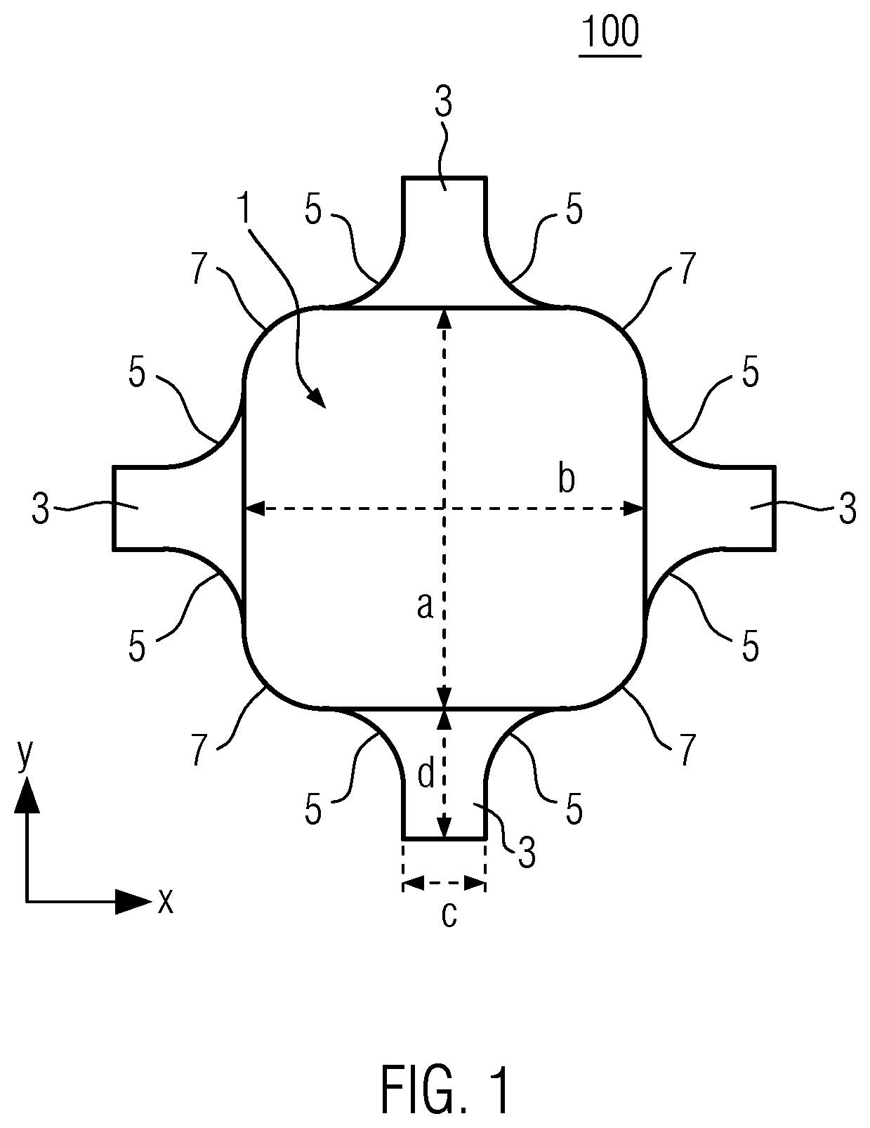
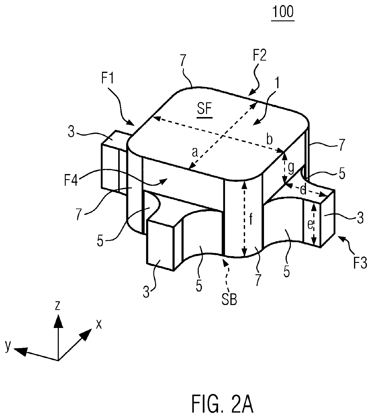
[0040]FIG. 1 depicts a schematic top view of a so-called unit cell 100 of a phononic crystal according to the present disclosure. FIG. 2A represents the corresponding stereoscopic side view of the unit cell 100 of FIG. 1. In FIG. 1, the unit cell 100 for a phononic crystal is shown. The unit cell 100 represent a single structure to be repeated in an array-like fashion for a phononic crystal. The unit cell 100 comprises a resonant mass 1, said resonant mass 1 mostly extending in a two-dimensional plane as shown in the top view of Figure. The two-dimensional plane is spanned in directions x and y as indicated by the corresponding coordinate system, it may therefore also be termed x-y plane. In the projection view of FIG. 1, the projection of resonant mass 1 exhibits the shape of a right Euclidean parallelogram, i.e. a rectangle. As is shown in FIG. 2A the resonant mass 1 is in fact a three-dimensional body and extends somewhat in a direction perpendicular to the drawing plane of FIG. ...


PUM


Abstract

Monolithic phononic crystal for vibration isolation comprising: a two-dimensional array of a plurality of resonant masses, said resonant masses being connected by bridges; wherein transition regions between bridges and resonant masses have a concave shape in the plane of the two-dimensional array, respectively; wherein the resonant masses each have convex edges in the plane of the two-dimensional array; wherein the bridges are recessed with respect to the thickness of the resonant masses.

Description

FIELD OF THE INVENTION[0001]The present invention relates to the field of vibration isolation systems and phononic crystals.BACKGROUND OF THE INVENTION[0002]Phononic crystals are periodic arrays of identical unit cells with local resonances in order to create a band gap intended to prevent propagation of sound at selected frequencies. The phononic crystal typically is a regular pattern of smaller elements, which provide a complete band gap in the ultrasonic frequency regime. The lack of available modes prevents vibrations of frequencies within the bandgap to travel through the device.[0003]For phononic crystals, see: Yan Pennec and Bahram Djafari-Rouhani, “Introduction to the Concept of Phononic Crystals and Their Band Structures”, in A. Khelif, A. Adibi (eds.), Phononic Crystals, Springer New York 2016. Phononic metamaterials and phononic crystals are also described, e.g., in U.S. Pat. No. 8,833,510 B2 or WO 2017 / 186765 A1.[0004]Alternative vibration isolations systems may comprise...

Claims


Application Information

Patent Timeline
IPC IPC(8): F16F7/104
CPCF16F2224/02F16F2222/08F16F7/104F16F2226/04F16F15/02G10K11/172
Inventor RIEDINGER, RALFDRAGOSITS, MATHIAS
Owner UNIVERSITY OF VIENNA
Learn More