Adjustable furniture

Pending Publication Date: 2020-05-21
MOTUS MECHANICS
View PDF0 Cites 5 Cited by
  • Summary
  • Abstract
  • Description
  • Claims
  • Application Information

AI Technical Summary

Benefits of technology

The patent text describes providing two connecting means to drive the support sections of a furniture mechanism. This results in a stronger structure under load, better control of the movements of the support sections, and more efficient use of the actuator. This allows for smoother operation and the use of smaller mechanisms, saving space in the furniture.

Problems solved by technology

In a modern domestic setting, where mattress thicknesses of 12 to 18 inches are common, and more typically 14 to 18 inches in the United States, the overall weight, stiffness and rigidity of the mattress can place an unacceptable load on the operating mechanism of the bed, for example thicker, heavier mattresses can cause the motor (actuator) to struggle and reduce the longevity of the motor and mechanism.
Motorized adjustable beds have been known to fail after a short number of cycles using mattresses of the afore-mentioned thickness.
However, this is not a practical solution for most applications.
Another problem associated with known designs is that the angle of elevation between the seat and the raised back support section is not ideal ergonomically, as it does not allow the mattress to naturally crease around the user's hip joint, so the user has to continually adjust their position as the backrest lifts.
A further problem associated with known designs is the requirement for the operating mechanism to be as compact as possible to free up space underneath the bed.
A further problem associated with known designs is the rigidity of the support section when under the weight of a user.
For example, a foot support section of the bed is vulnerable to the weight of the user and can require additional bracing to increase the rigidity.

Method used


Image

  • Adjustable furniture
  • Adjustable furniture
  • Adjustable furniture

Examples


Embodiment Construction

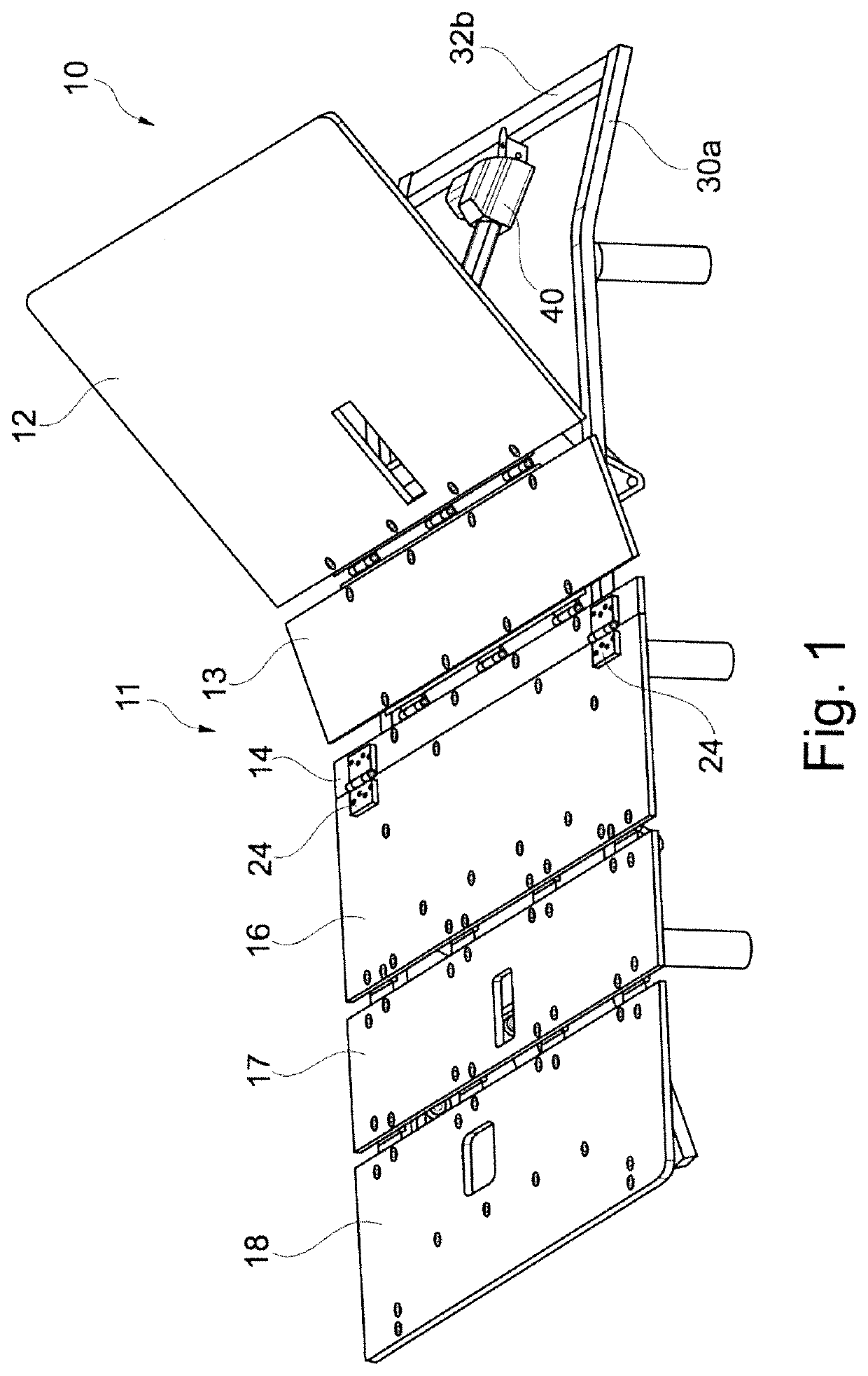
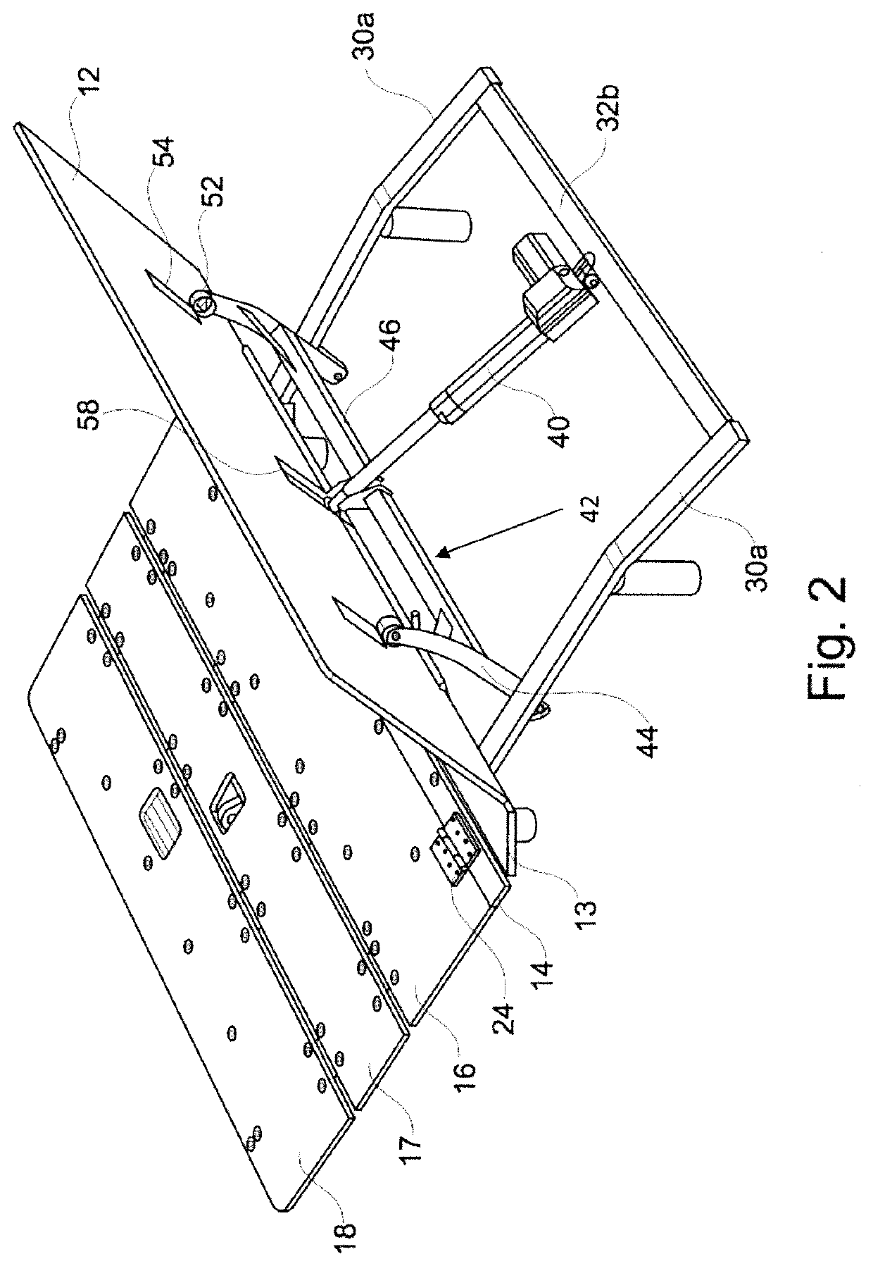
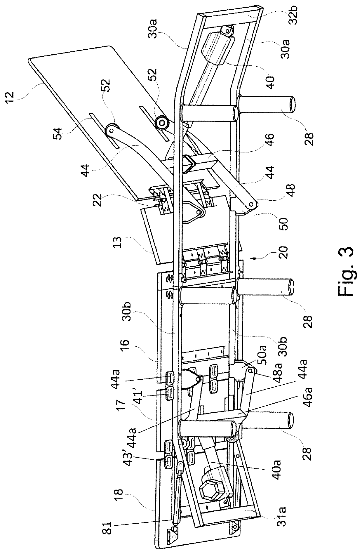
[0034]Reference will now be made in detail to embodiments of the invention. Wherever possible, same or similar reference numerals are used in the drawings and the description to refer to the same or like parts or steps. The drawings are in simplified form and are not to precise scale. The word ‘couple’ and similar terms do not necessarily denote direct and immediate connections, but also include connections through intermediate elements or devices. For purposes of convenience and clarity only, directional (up / down, etc.) or motional (forward / back, etc.) terms may be used with respect to the drawings. These and similar directional terms should not be construed to limit the scope in any manner. It will also be understood that other embodiments may be utilized without departing from the scope of the present invention, and that the detailed description is not to be taken in a limiting sense, and that elements may be differently positioned, or otherwise noted as in the appended claims wi...


PUM


Abstract

An article of adjustable furniture includes a plurality of articulated support sections, said support sections including at least one adjustable first support section and at least one adjustable second support section, and an actuator mechanism for effecting co-ordinated pivotal movement to angularly adjust the at least one adjustable first support section relative to the at least one adjustable second support section, in which the actuator mechanism is operable to drive a first connecting means to act directly on the first support section, and a second connecting means to act directly on the second support section or a pivotal point connecting the first and second support sections such that the actuator mechanism simultaneously drives both support sections.

Description

CROSS REFERENCE TO RELATED APPLICATIONS[0001]This application is a continuation (CON) of PCT Ser. No.: PCT / GB2018 / 052150 (WO 2019 / 021025) filed Jul. 27, 2018, the entire contents of which are incorporated herein by reference, which in turn claims priority to GB 1712186.4 filed Jul. 28, 2017.[0002]This application is also a continuation-in-part (CIP) of U.S. Ser. No. 15 / 557,192 filed Sep. 11, 2017, the entire contents of which are incorporated herein by reference, which is a 371 National Phase of PCT / EP2016 / 055381 filed Mar. 11, 2016, the entire contents of which are incorporated herein by reference, which claims priority to GB 1504140.3 filed Mar. 11, 2015.[0003]This application is also a continuation-in-part (CIP) of U.S. Ser. No. 16 / 307,530 filed Dec. 6, 2018, the entire contents of which are incorporated herein by reference, which is a 371 National Phase of PCT / GB2017 / 051722 filed Jun. 13, 2017, the entire contents of which are incorporated herein by reference, which claims prior...

Claims


Application Information

Patent Timeline
IPC IPC(8): A47C1/024A47C7/50A47C7/40A47C7/46
CPCA47C1/0242A47C7/402A47C7/462A47C7/5068A47C20/041A61G7/018A61G7/015
Inventor BROWN, PAUL
Owner MOTUS MECHANICS
Why Eureka
Try Eureka