Member-to-member laminar fuse connection

a laminar fuse and fuse connection technology, applied in the field of assembly, can solve the problems of limited strength and deformation capacity between structural members, and achieve the effects of damping, inelastic stiffness, and elastic stiffness

Active Publication Date: 2020-05-21
SIMPSON STRONG TIE
View PDF0 Cites 0 Cited by
  • Summary
  • Abstract
  • Description
  • Claims
  • Application Information

AI Technical Summary

Benefits of technology

[0007]In another embodiment, material including, but not limited to, elastomer, polymers and reinforced polymers, concrete or cementitious grout or other known materials may be place

Problems solved by technology

In each of these cases, the strength and deformation capacity between structural members is limited

Method used


Image

  • Member-to-member laminar fuse connection
  • Member-to-member laminar fuse connection
  • Member-to-member laminar fuse connection

Examples


Embodiment Construction

[0018]The following detailed description of the present invention references the accompanying drawing figures that illustrate specific embodiments in which the invention can be practiced. The embodiments are intended to describe aspects of the present invention in sufficient detail to enable those skilled in the art to practice the invention. Other embodiments can be utilized and changes can be made without departing from the spirit of the scope of the present invention. The present invention is defined by the appended claims and, therefore, the description is not to be taken in a limiting sense and shall not limit the scope of the equivalents to which such claims are entitled.

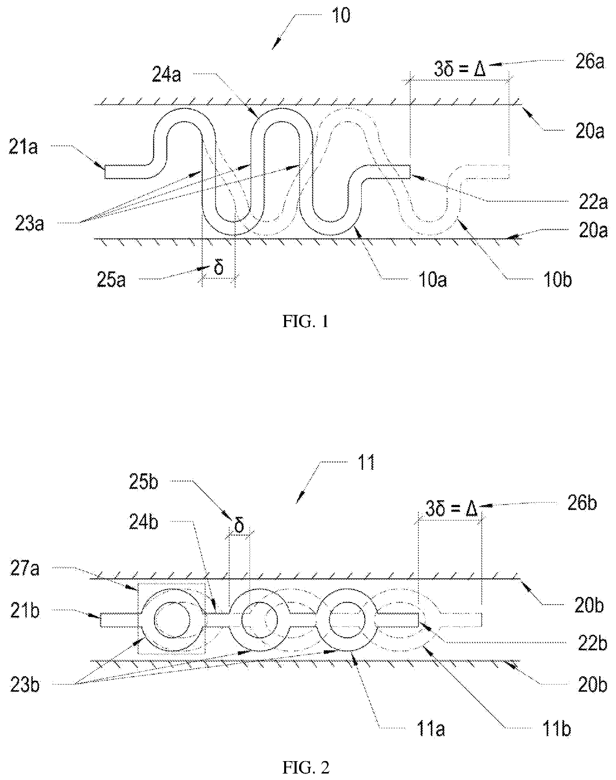
[0019]As illustrated in FIG. 1, a connection bracket 10 of the present invention is shown wherein connection bracket 10 includes a first connection element 21a, a second connection element 22a, and a series of fuse elements 23a interconnected by interconnection elements 24a disposed between first and second co...


PUM


Abstract

A member-to-member planar connection bracket that includes multiple repeated fuse element configurations that each provide a pre-determined inelastic load-carrying capacity and a reliable inelastic deformation capacity upon development of one or more inelastic hinge locations within the fuse elements. The fuse configurations are interconnected in series such that the total deformation accommodated between first end of the bracket and second end of the bracket is the sum of deformations accommodated by the individual fuse configurations. Multiple brackets are configured in laminar configurations and interconnected to create a connection assembly provides increased strength or increased deformation capacity as compared to an individual bracket. The connection assembly is used to connect a first structural member and second structural member. The pre-determined maximum inelastic load-carrying capacity of the assembly is less than the elastic load-carrying capacity of the first structural member and the second structural member.

Description

TECHNICAL FIELD[0001]The present invention relates to an assembly used to facilitate a member-to-member connection for structural load resisting systems, such as, but not limited to, seismic and progressive collapse structural load resisting systems.BACKGROUND ART[0002]Several devices, or brackets, have been developed for structural applications wherein relatively large deformations between two members are accommodated by inelastic flexural deformations (rotations) within individual elements of the connecting device. The uniqueness of these devices is that structural integrity, or load carrying capacity, between the members is maintained and predictable by use of an elastic-inelastic or elastic-plastic material, such as steel. Examples of such devices are provided in patent applications US2002 / 0184836 A1, PCT / US2011 / 042721, U.S. Pat. No. 8,683,758 B2, and U.S. Pat. No. 9,514,907 B2. In each of these cases, the strength and deformation capacity between structural members is limited b...

Claims


Application Information

Patent Timeline
IPC IPC(8): E04H9/02
CPCE04H9/021E04H9/0215E04H9/0237E04H9/0235E04C2003/0465E04B2001/2415E04B1/2403
Inventor MCMANUS, PATRICKPUCKETT, JAYPETERSEN, JACK
Owner SIMPSON STRONG TIE
Why Eureka
Try Eureka