Aircraft fuel tank aperture sealing

a technology for aircraft fuel tanks and apertures, which is applied in mechanical equipment, transportation and packaging, and spars/stringers, etc. it can solve the problems of causing unwanted drilling swarfs, complicated procedures, and requiring the assembly of seal plates with the wings, and achieves the effect of easy sealing

Active Publication Date: 2020-05-28
AIRBUS OPERATIONS LTD
View PDF0 Cites 4 Cited by
  • Summary
  • Abstract
  • Description
  • Claims
  • Application Information

AI Technical Summary

Benefits of technology

[0014]The saddle, in particular, may comprise slightly flexible or resilient material, more easily to make a seal with the first seal part. The

Problems solved by technology

This complex procedure is necessary owing to the stringer being positioned dimensionally within the aperture only to within certain height, longitudinal and lateral positioning tolerances.
Such fitting of the seal plates with the wing assembled is extremely time-consuming, creates unwanted drilling swarf and does not allow easy access for drilling or fitting, owing to restricted access within the wing.
Working within a wing box is also undesirable from a health and safety perspective.
Increased inspection and re-work can also result and the use of CNC drilling machines for the task i

Method used


Image

  • Aircraft fuel tank aperture sealing
  • Aircraft fuel tank aperture sealing
  • Aircraft fuel tank aperture sealing

Examples


Embodiment Construction

[0059]For ease of understanding, like reference numerals will be used for equivalent features in the drawings. With reference to FIG. 15, according to the prior art and showing the general arrangement of an aircraft wing, a wing lower cover 62 is shown, braced by stringers 14 and ribs 1. Not shown are an upper cover which will be attached to upper edges 63 of the ribs 1 and front and rear spars which will be attached to forward and rear edges of the ribs, respectively. The ribs 1 define “mousehole” apertures 2 therein. The ribs are made of metal but may be made of carbon fibre reinforced composite material. The ribs 1 have rib feet 3a, 3b, and upstanding webs 4.

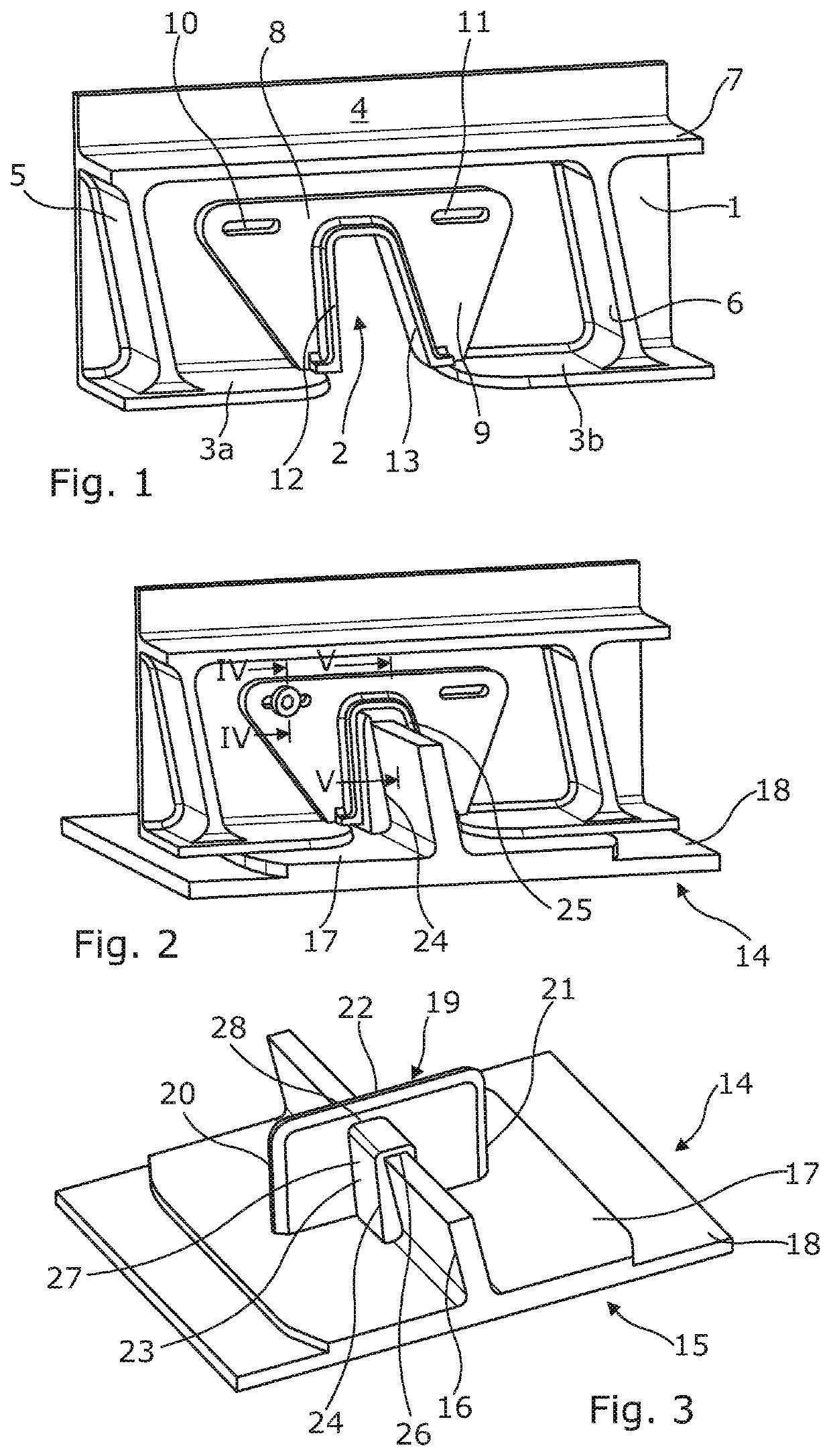
[0060]In FIG. 1, according to the invention, a rib 1 has similar features to those shown in FIG. 15, and in addition two vertical braces 5, 6 and a horizontal brace 7.

[0061]Surrounding the aperture 2 is a first seal part in the form of a seal plate 8. The seal plate 8 is here made of fibre reinforced composite material and ha...


PUM


Abstract

A seal for sealing an aircraft fuel tank, an aircraft wing rib and stringer sealing assembly, an aircraft wing fuel tank, an aircraft structural wing box, an aircraft wing, and a method of sealing an aperture are disclosed. The seal is for sealing a wing rib to a stringer passing through an aperture in the rib at a variable position in the aperture. The seal includes self-adjustment means to absorb any tolerance when forming the seal, upon the stringer being assembled into the aperture in the rib.

Description

FIELD OF THE INVENTION[0001]The present invention relates to an apparatus and method for aircraft fuel tank aperture sealing.BACKGROUND[0002]Modern aircraft, in particular commercial aircraft, carry fuel in one or more compartments in the fuselage, wing or tailplane. In the wing or tailplane, the fuel is not sealed within a separate internal tank but is housed directly within the structural box of the wing or tailplane. An aircraft wing box traditionally comprises an upper and a lower aerodynamically shaped wing cover separated by front and rear spars and sometimes a central spar for the wing box. Spaced spanwise of the wing are a series of ribs each of which extends horizontally between front and rear spars and vertically between upper and lower covers. The ribs are fastened to both covers and spars whereby to provide all round support for the wing structure. Thus the ribs effectively divide the span of the wing into a series of compartments.[0003]Complication arises with the need ...

Claims


Application Information

Patent Timeline
IPC IPC(8): B64C3/34B64C3/18
CPCF16J15/104B64C3/34B64C3/182B64C3/187F16J15/062B64D37/04B64D37/005B64D37/08B64D37/06B64C3/18B64F5/10B64C7/00
Inventor EDWARDS, PAULPEACOCK, ANTONYSANDERSON, TIMOTHY
Owner AIRBUS OPERATIONS LTD
Why Eureka
Try Eureka