
Infusion pipe

Pending Publication Date: 2020-06-11
MANI INC
View PDF4 Cites 0 Cited by
  • Summary
  • Abstract
  • Description
  • Claims
  • Application Information

AI Technical Summary

Benefits of technology

The present invention provides an infusion pipe that has a higher flow rate compared to a pipe with a circular cross-section, and is easier to join with a cannula.

Problems solved by technology

As a result, there is a problem that the water passing through the insertion part 111 of the infusion pipe 110, which is thinner than the cannula piercing part 21a, consequently becomes a small amount.

Method used


Image

  • Infusion pipe
  • Infusion pipe
  • Infusion pipe

Examples


Embodiment Construction

[0019]An embodiment according to the present invention is described below with reference to accompanying drawings.

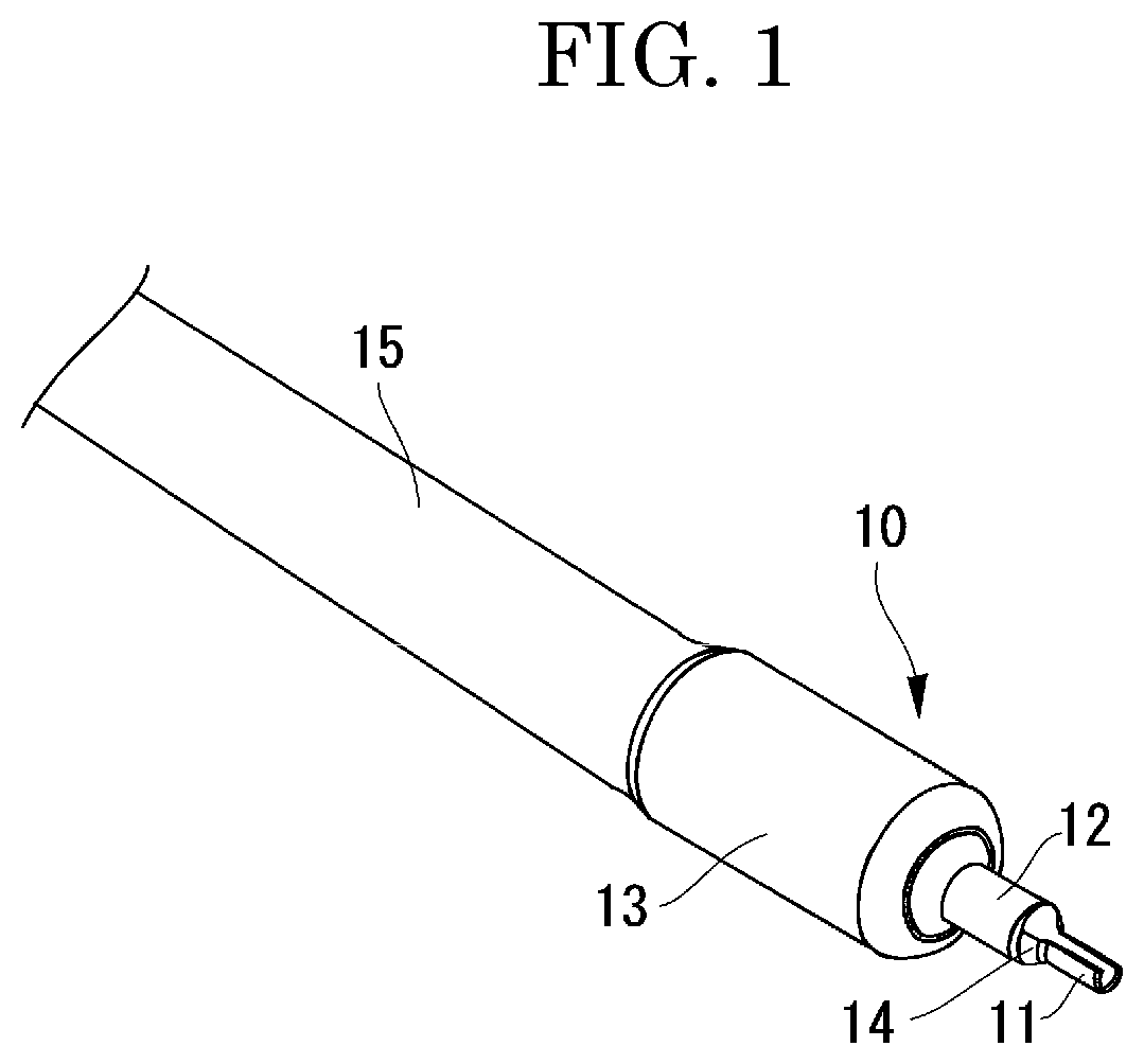
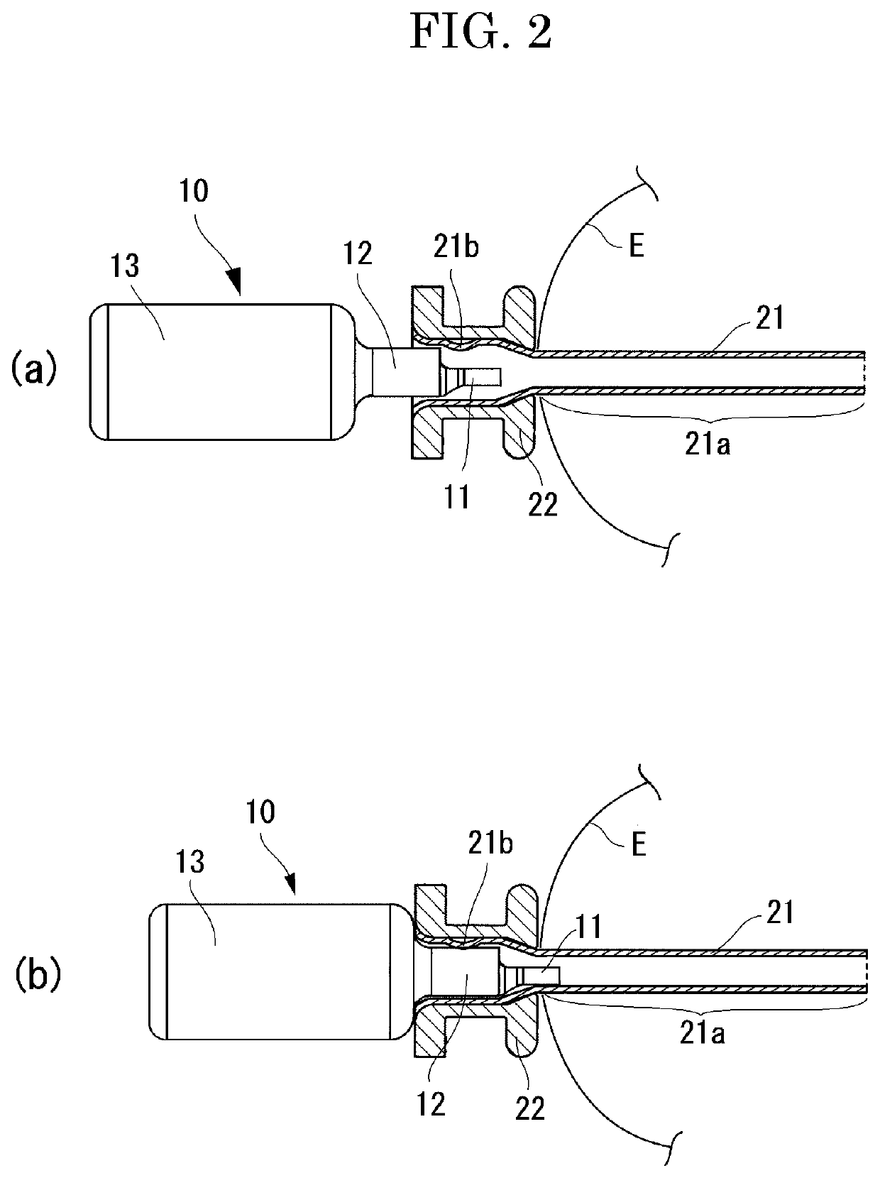
[0020]FIG. 1 is an oblique view of an infusion pipe of the present invention. In addition, FIG. 2 is a diagram describing joining of the infusion pipe of the present invention and a cannula, wherein FIG. 2(a) illustrates a state during the joining process and FIG. 2(b) illustrates the state after the joining process. A cannula 20 for joining an infusion pipe 10 is made by fitting a metal cannula pipe 21 into a resin cannula base 22, as with the conventional cannula. Moreover, the cannula pipe 21 has a portion fit in the cannula base 22 as a cannula joining part 21b, and a portion pierced in an eyeball E as a cannula piercing part 21a.

[0021]The basic configuration of the infusion pipe 10 similarly to the conventional pipe has an insertion part 11 to be inserted inside the cannula piercing part 21a, the joining part 12 to be pressed and secured by the cannula joining part...


PUM


Abstract

An infusion pipe capable of achieving a flow rate higher or the same as that of a conventional product, and of easily joining to a cannula attached to an eyeball. The infusion pipe of the present invention is used in an ophthalmic operation with the infusion pipe joined to a cannula attached to an eyeball, and includes an insertion part to be inserted, at the time of joining to the cannula, inside a cannula piercing part, which is a part of the cannula for piercing the eyeball. A cross-section of the insertion part is an arc shape from which a part of a circle is cut out.

Description

TECHNICAL FIELD[0001]The present invention relates to an infusion pipe used in an ophthalmic operation with the infusion pipe joined to a cannula attached to an eyeball.BACKGROUND ART[0002]Vitreous surgery is surgery for cutting and removing a gelatinous vitreous body within the eyeball or a proliferative membrane formed on the retina through degeneration of the vitreous body. Such an ophthalmic operation is performed while irrigating inside the eyeball with water using an infusion cannula.[0003]The infusion cannula has a tube allowing the perfusing water to pass through, and an infusion pipe connecting the tube and the cannula. FIG. 5 is an oblique view of an infusion pipe of a conventional product. FIG. 6 is a diagram describing joining of a cannula and an infusion pipe of the conventional product, wherein FIG. 6(a) illustrates a state during the joining process and FIG. 6(b) illustrates the state after the joining process. Note that illustration of a tube 15 is omitted from FIG. ...

Claims


Application Information

Patent Timeline
IPC IPC(8): A61F9/00
CPCA61F9/0017A61F9/00736
Inventor MURAKAMI, ETSUOTAKANO, MASAHIRO
Owner MANI INC
Features
  • Generate Ideas
  • Intellectual Property
  • Life Sciences
  • Materials
  • Tech Scout
  • Unparalleled Data Quality
  • Higher Quality Content
  • 60% Fewer Hallucinations
Learn More