Magnetic filter for a central heating system

a technology for central heating and filters, applied in lighting and heating apparatus, heating types, separation processes, etc., can solve the problems of limited attempts to reduce the overall fitted size of filters, leakage of seals, and difficult fitting of valves and filters in tight spaces, so as to prevent overtightening and limit the compression of o-rings

Active Publication Date: 2020-06-11
ADEY HLDG
View PDF1 Cites 5 Cited by
  • Summary
  • Abstract
  • Description
  • Claims
  • Application Information

AI Technical Summary

Benefits of technology

[0007]Filters typically need to be opened for cleaning, i.e. to remove captured magnetic particles. The separation chamber is normally closed by a lid, and an O-ring seal is provided between the lid and the canister to provide a watertight and gastight seal when the separation chamber is closed. The lid is typically attached to the separation chamber by means of a screw thread. When the lid is tightened, the O-ring is compressed. The O-ring reacts by pushing the lid and the separation chamber away from each other which puts tension in the thread, preventing the lid from unscrewing for example due to vibration. However, if the lid is overtightened onto the O-ring then the seal may be damaged. Some filters have been produced with stop faces to limit compression of the O-ring and prevent overtightening. However, this also limits the ability of the O-ring to lock the screw thread and prevent the lid from coming undone due to vibration. It is a further object of the invention to solve this problem.

Problems solved by technology

As well as the requirement for the filter to fit within the space once installed, installations with limited space can also present challenges for the installer to access the installation space and effect the installation.
Fitting the valves and the filter in a tight space can be difficult.
Furthermore, attempts to reduce the overall fitted size of the filter have been limited by the need to provide a pair of valves on the inlet and outlet.
However, if the lid is overtightened onto the O-ring then the seal may be damaged.
However, this also limits the ability of the O-ring to lock the screw thread and prevent the lid from coming undone due to vibration.

Method used


Image

  • Magnetic filter for a central heating system
  • Magnetic filter for a central heating system
  • Magnetic filter for a central heating system

Examples


first embodiment

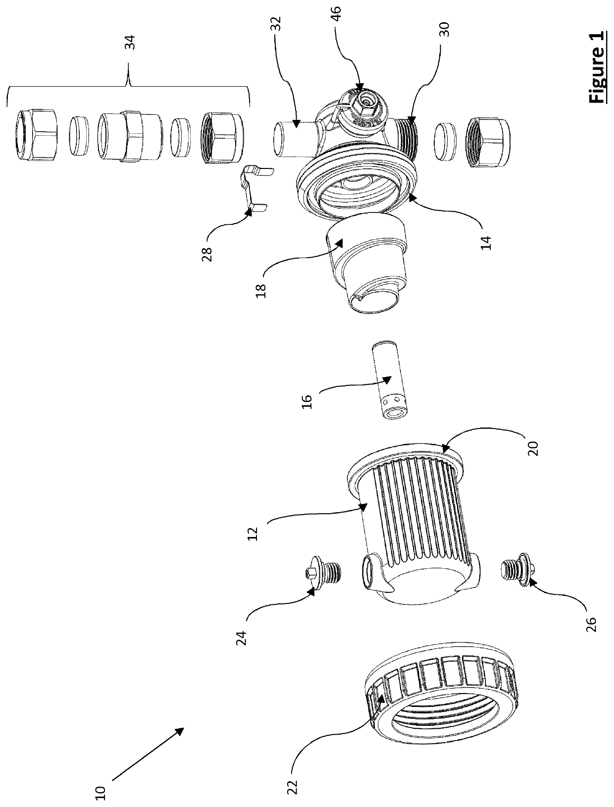
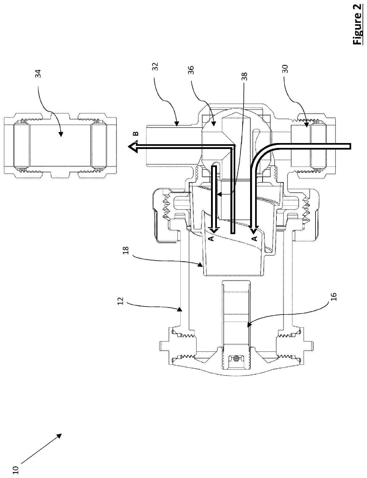
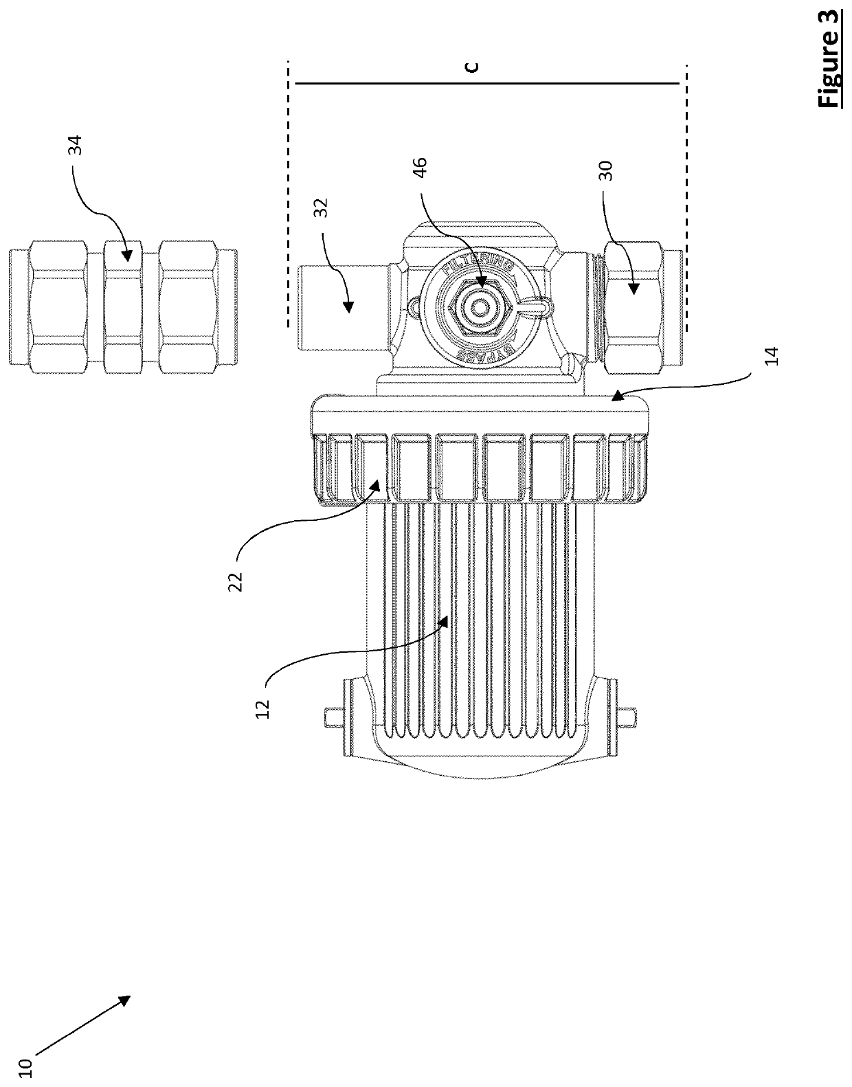
[0039]Referring firstly to FIG. 1, a magnetic filter is indicated generally at 10. The filter includes a separation chamber in the form of a canister 12. The canister 12 is open at one end, and the open end fits onto a fitment 14 which closes the canister 12. The separation chamber contains a magnet 16 which in use attracts and retains magnetic particles to clean the central heating system water. A flow director 18 is provided which causes flow entering the separation chamber 12 from the fitment 14 to swirl, and also directs the flow to enhance the effectiveness of separation by ensuring that a substantial proportion of the flow will come close enough to the magnet for particles to be captured. The flow director is disposed at the interface between the fitment 14 and the separation chamber 12.

[0040]A flange 20 is provided around the open end of the canister 12. A threaded ring 22 sits behind the flange (i.e. on the opposite side of the flange 20 to the fitment 14). The threaded ring...

second embodiment

[0044]Referring now to FIG. 2, flow paths through the filter 10 will be described in more detail. A single ball valve 36 is provided between the inlet 30, the outlet 32 and the separation chamber 12. In FIG. 2 the ball valve is shown in a first position in which the inlet 30 is fluidly connected to the separation chamber 12 and the outlet 32 is also fluidly connected to the separation chamber 12. The valve 36 is also movable into a second position where the separation chamber is isolated from the inlet and the outlet (see FIG. 6, second embodiment, the valve arrangement is the same). The valve is movable by means of an external handle (46, FIG. 1). With the valve 36 in the first position, central heating system water enters through the inlet 30, through a passage in the valve 36, and enters the separation chamber 12 through a ring-shaped interface (arrows A). On entry to the separation chamber 12, the flow director 18 causes the water to swirl, and also directs a substantial portion...


PUM

PropertyMeasurementUnit
distanceaaaaaaaaaa
sizesaaaaaaaaaa
sizeaaaaaaaaaa

Abstract

A magnetic filter for a central heating system is disclosed, the filter including a separation chamber, a magnet for capturing magnetic particles within the separation chamber, an inlet for fluidly connecting to a central heating system circuit, an outlet for fluidly connecting to a central heating system circuit, and a single valve operable to select between at least two positions, the valve in a first position fluidly connecting the inlet to the separation chamber and fluidly connecting the outlet to the separation chamber and the valve in a second position isolating both the inlet and the outlet from the separation chamber.

Description

[0001]The present invention relates to a magnetic filter for use in a central heating system.BACKGROUND TO THE INVENTION[0002]It is now common to fit magnetic filters to central heating systems to remove magnetic contamination from the system water, and in turn prevent damage to the boiler which can otherwise be caused when debris builds up in the heat exchanger. Filters are available in a variety of sizes, but in some installations where there is limited space, in particular underneath or above a boiler, there is still a demand for a smaller filter.[0003]As well as the requirement for the filter to fit within the space once installed, installations with limited space can also present challenges for the installer to access the installation space and effect the installation.[0004]Typically with existing filters, a section of pipe on the return side of the heating system circuit, close to the boiler, needs to be removed. The filter is then fitted into the heating system circuit via a ...

Claims


Application Information

Patent Timeline
Patent Type & Authority Applications(United States)
IPC IPC(8): B03C1/033B03C1/28F24D19/00
CPCB03C2201/28F24D19/0092B03C1/0332B03C2201/18B03C1/288B03C1/286B01D35/06B01D35/30B03C1/00C02F1/48B01D35/147
Inventor DOWNIE, SIMONLEUNG, KELVIN
Owner ADEY HLDG
Why Eureka
Try Eureka