Pedal apparatus for vehicle

a technology for pedals and vehicles, applied in the direction of mechanical control devices, process and machine control, instruments, etc., can solve the problems of increasing increasing and limited space below the driver's seat, so as to reduce the fatigue of the driver and increase the injury of the driver

Active Publication Date: 2020-06-11
HYUNDAI MOTOR CO LTD +1
View PDF0 Cites 10 Cited by
  • Summary
  • Abstract
  • Description
  • Claims
  • Application Information

AI Technical Summary

Benefits of technology

[0007]Various aspects of the present invention are directed to providing a pedal apparatus configured for a vehicle, in which a brake pedal and an accelerator pedal are provided in a single pedal housing to operate in the same direction thereof. A relatively-larger space may be provided below the driver's seat, reducing the fatigue of the driver. The pedal apparatus can minimize a phenomenon in which the injury of a driver may be increased by the pedals in the event of an accident.
[0008]Also provided is a pedal apparatus configured for a vehicle, in which both the accelerator pedal and the brake pedal provided in the single pedal housing are configured to operate in the same direction toward the front, so that a different sensation in the operation of the pedals may be removed. The operation of the accelerator pedal the operation of the brake pedal may be clearly distinguished, advantageously preventing an erroneous operation from being performed by the driver.
[0017]The pedal apparatus may further include: a guide groove provided in one side surface of the pedal housing to extend along a radius of rotation of the brake pedal; a flange protruding from the brake pedal toward the guide groove; and a stopper pin having one end portion coupled to the flange and the other end portion inserted into the guide groove, the stopper pin being configured to move along the guide groove to guide pivoting of the brake pedal while preventing the brake pedal from being separated from the pedal housing when the brake pedal is operated.
[0023]As set forth above, the pedal apparatus configured for a vehicle according to an exemplary embodiment of in various aspects of the present invention, both the accelerator pedal and the brake pedal are provided in the single pedal housing, so that the number of components and fabrication costs may be reduced. Since only the single pedal housing is disposed, a relatively-larger space may be provided below the driver's seat. The reduced number of components can advantageously minimize a phenomenon in which the injury of a driver is increased by the pedals.
[0025]Furthermore, according to an exemplary embodiment of the present invention, the accelerator pedal is operated by the front portion of the foot, in a manner similar to the manner in which a pendant type pedal apparatus of the related art is operated, while the brake pedal is operated by the entire portions of the foot, in a manner similar to the manner in which a pedal device in the shape of an organ pedal is operated. Accordingly, the pedal apparatus according to an exemplary embodiment of in various aspects of the present invention, the operation of the accelerator pedal and the operation of the brake pedal may be clearly distinguished from each other, advantageously preventing an erroneous operation from being performed by the driver.
[0026]Furthermore, the pedal apparatus according to an exemplary embodiment of the present invention may be implemented as an electronic pedal device, which may be advantageously used in vehicles provided with an electronic brake system or vehicles provided with an in-wheel propulsion system.

Problems solved by technology

The space below the driver's seat is limited, due to the accelerator pedal and the brake pedal being disposed therein, increasing the fatigue of the driver.
The injury of the driver may be increased by the two pedals, which is problematic.
In such cases, however, the accelerator pedal and the brake pedal are operated in different directions, so that a different sensation in the operation of the pedals may be caused.
The different sensation may cause an erroneous operation to be performed by the driver, which is problematic.

Method used


Image

  • Pedal apparatus for vehicle
  • Pedal apparatus for vehicle
  • Pedal apparatus for vehicle

Examples


Embodiment Construction

[0040]Reference will now be made in detail to various embodiments of the present invention(s), examples of which are illustrated in the accompanying drawings and described below. While the invention(s) will be described in conjunction with exemplary embodiments, it will be understood that the present description is not intended to limit the invention(s) to those exemplary embodiments. On the other hand, the invention(s) is / are intended to cover not only the exemplary embodiments, but also various alternatives, modifications, equivalents and other embodiments, which may be included within the spirit and scope of the invention as defined by the appended claims.

[0041]Hereinafter, a pedal apparatus configured for a vehicle according to exemplary embodiments of the present invention will be described in detail with reference to the accompanying drawings. Throughout the drawings, the same reference numerals will refer to the same or like parts.

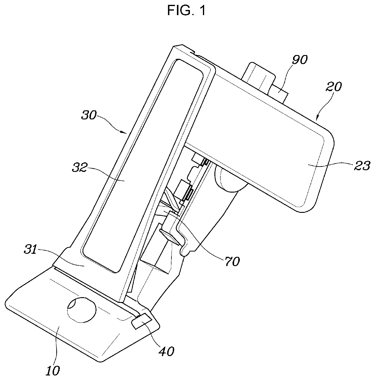
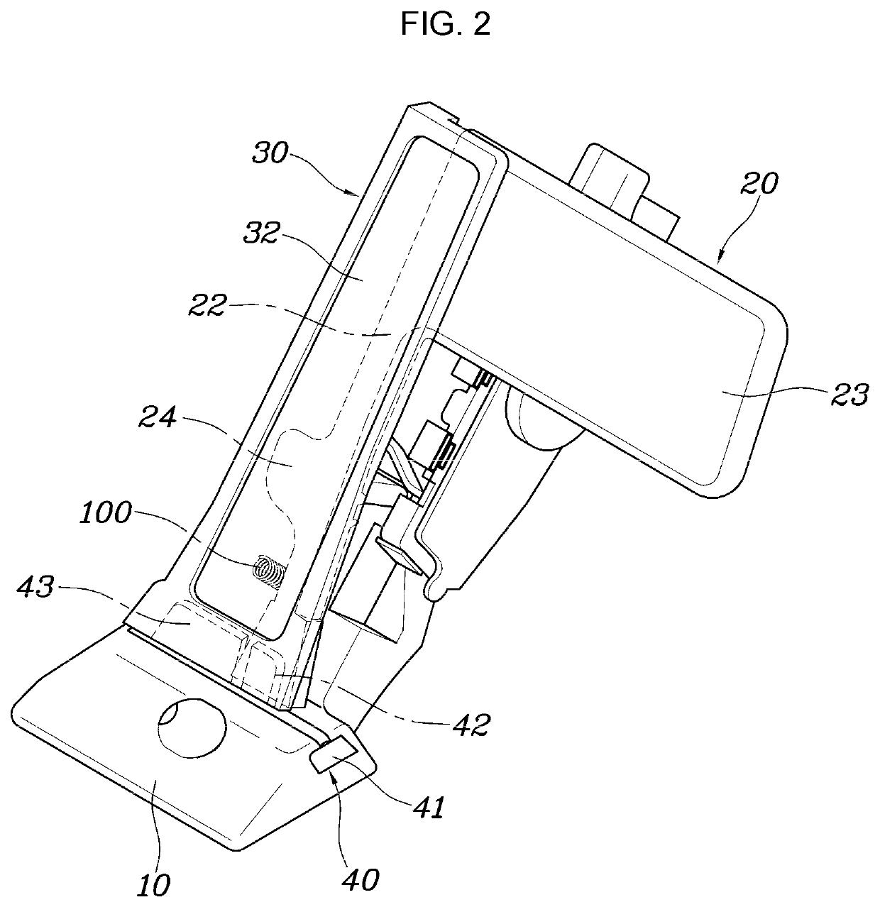
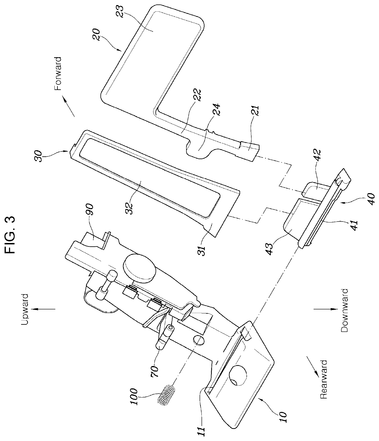
[0042]As illustrated in FIG. 1, FIG. 2, FIG. ...


PUM


Abstract

A pedal apparatus for a vehicle may include a pedal housing fixedly disposed in a space in which a driver's foot is located; and an accelerator pedal and a brake pedal pivotably connected to the pedal housing, wherein, when the accelerator pedal is operated, the accelerator pedal pivots independently of the brake pedal, and when the brake pedal is operated, both the brake pedal and the accelerator pedal pivot.

Description

CROSS REFERENCE TO RELATED APPLICATION[0001]The present application claims priority to Korean Patent Application No. 10-2018-0158667, filed Dec. 10, 2018, the entire contents of which is incorporated herein for all purposes by this reference.BACKGROUND OF THE INVENTIONField of the Invention[0002]The present invention generally relates to a pedal apparatus for a vehicle and, more particularly, to a pedal apparatus for a vehicle, in which a brake pedal and an accelerator pedal are provided in a single pedal housing so as to operate in the same direction.Description of Related Art[0003]In typical vehicles, an accelerator pedal for accelerating a vehicle and a brake pedal for braking the vehicle are disposed in a space below a driver's seat such that the accelerator pedal and the brake pedal are respectively operated by a driver's foot.[0004]The space below the driver's seat is limited, due to the accelerator pedal and the brake pedal being disposed therein, increasing the fatigue of th...

Claims


Application Information

Patent Timeline
Patent Type & Authority Applications(United States)
IPC IPC(8): G05G1/30B60K26/02B60K26/04G05G1/38G05G1/44G05G5/05B60T7/06B60T7/04
CPCG05G1/30G05G1/305B60T7/042B60K26/02B60K2026/046B60T7/06G05G5/05B60K7/0007B60K26/04G05G1/38G05G1/44G05G2505/00G05G1/01B60Y2300/43B60Y2302/09B60Y2400/81G05G1/32G05G1/36G05G5/03
Inventor KIM, EUN SIK
Owner HYUNDAI MOTOR CO LTD
Why Eureka
Try Eureka