A drop tube and a rotary parlour feeding provided with such a drop tube

a drop tube and parlour technology, applied in the field of drop tubes and rotary parlour feeding provided with such drop tubes, can solve problems such as off-bouncing problems, and achieve the effect of reducing the speed of furthering

Active Publication Date: 2020-06-18
DELAVAL HLDG AB
View PDF3 Cites 1 Cited by
  • Summary
  • Abstract
  • Description
  • Claims
  • Application Information

AI Technical Summary

Benefits of technology

[0012]According to one embodiment, the tubular mid-section has a centre axis, and the centre axis of the tubular end section extends with an angle β in relation to the centre axis of the tubular mid-section. This design promotes positioning of the tubular end section with the opening thereof turned downwards towards a food manger. It also means that the drop tube subjects food or nutrients flowing through the drop tube for yet another change of direction apart from the one caused by the above-mentioned end wall, which contributes to further speed reduction. According to one embodiment, said angle β is at least 100°. According to an alternative embodiment, said angle β is in the range of 120°-145°.
[0013]According to one embodiment, the tubular connection section is more flexible than the tubular mid-section and the tubular end section. The tubular connection section is flexible enough to allow an angular set off of 10°, preferably 20° of the drop tube from a positioned in which it is fixed to and extending from a food container, without any remaining plastic deformation of the tubular connection section. Thereby, certain disposition of the drop tube, for example caused by an animal getting in touch with the tubular end section of the drop tube, is permitted without permanent deformation of the drop tube. It is regarded as positive to let the mid-section and the end section of the drop tube to be relatively rigid, while the elastic deformation is adopted by the tubular connection section.

Problems solved by technology

If the opening is too small, the flow rate will be insufficient, and if it is too big there will still be off-bouncing problems due to high speed flowing of food and nutrients out of the drop tube.

Method used


Image

  • A drop tube and a rotary parlour feeding provided with such a drop tube
  • A drop tube and a rotary parlour feeding provided with such a drop tube
  • A drop tube and a rotary parlour feeding provided with such a drop tube

Examples


Embodiment Construction

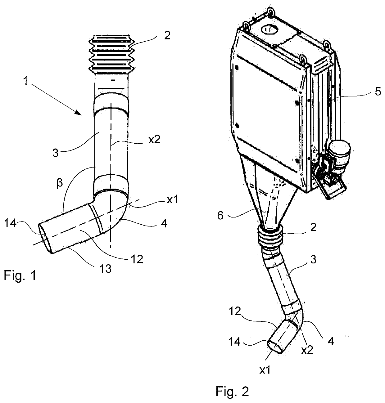
[0034]FIG. 1 shows a first embodiment of a drop tube 1 according to the invention. The drop tube 1 comprises a tubular connection section 2 configured to be connected to a food container (indicated with 5 in FIG. 2), a tubular mid-section 3, which in a first end is connected to the connection section 2, and a tubular end section 4, which is connected to a second end of the tubular mid-section 3.

[0035]FIG. 2 shows an animal feeding device comprising a food container 5 and the drop tube 1 shown in FIG. 1. The food container 5 comprises a food outlet tube 6 to which the tubular connection section 2 of the drop tube 1 is connected.

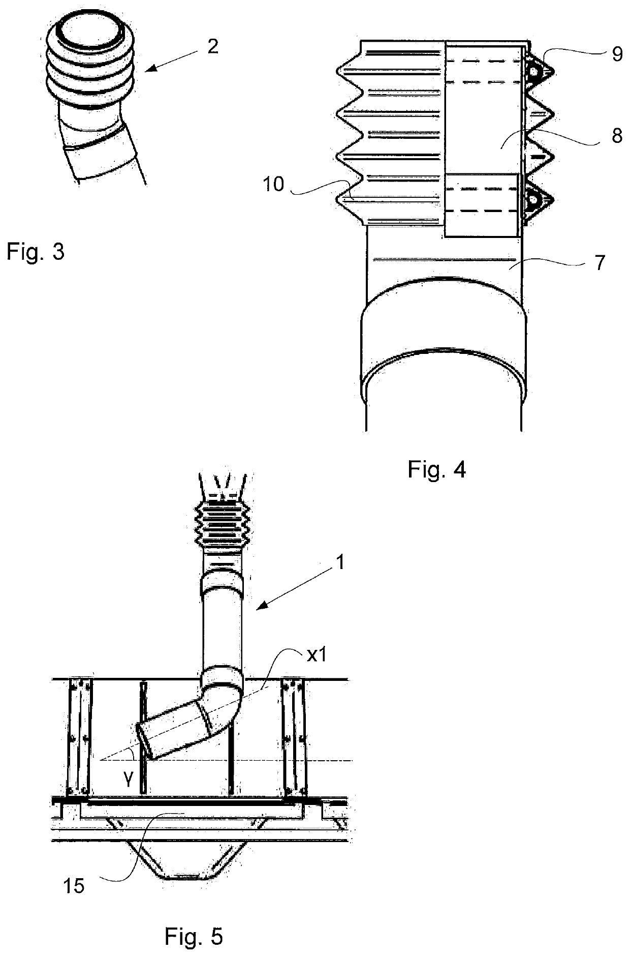
[0036]The tubular connection section 2 is shown in detail in FIGS. 3 and 4, and comprises a tube 7 made of a polymer suitable for the purpose, preferably PVC, which is connected to the tubular mid-section 3 by a tube fitting joint. At an opposite end of the tubular connection section 2, and connected to the PVC-tube, the connection section 2 comprises an elast...


PUM


Abstract

A drop tube for providing food to an animal in a milking stable, the drop tube configured to receive food from a food container arranged vertically above the drop tube and to deliver the received food into a food manger, the drop tube including a tubular connection section to connect to a food container, a tubular mid-section with a first end connected to the connection section, and a tubular end section connected to a second end of the tubular mid-section, the tubular end section having a centre axis and presenting an opening in a tubular wall portion of the tubular end section, and the tubular end section has an end wall which is intersected by the centre axis of the tubular end section.

Description

TECHNICAL FIELD[0001]The present invention relates to a drop tube arranged to provide food to an animal in a milking stable, said drop tube being configured to receive food from a food container arranged vertically above the drop tube and to deliver the received food into a food manger, said drop tube comprising a tubular connection section configured to be connected to a food container, a tubular mid-section, which in a first end is connected to the connection section, and a tubular end section, which is connected to a second end of the tubular mid-section.[0002]The present invention also relates to a rotary parlour provided with a feeding device comprising such a drop tube.BACKGROUND ART[0003]In milking stables for the milking of cows, in particular so called rotary parlours, there may be provided a food manger and a feeding device for providing food to the food manger. The feeding device usually comprises a container from which a drop tube extends towards the food manger. At the ...

Claims


Application Information

Patent Timeline
Patent Type & Authority Applications(United States)
IPC IPC(8): A01K5/02
CPCA01K5/0225
Inventor CHODACKI, ARTUR
Owner DELAVAL HLDG AB
Why Eureka
Try Eureka