Expanding anchor

a technology of expanding anchors and screws, applied in the field of expanding anchors, can solve the problems of high failure rate, difficult screw or anchor insertion,

Pending Publication Date: 2020-06-18
CONMED CORP
View PDF0 Cites 0 Cited by
  • Summary
  • Abstract
  • Description
  • Claims
  • Application Information

AI Technical Summary

Benefits of technology

The present invention provides an anchoring system for a knee ligament reconstruction that can secure a graft within a bone tunnel. The system includes an anchor having a conical head and a plurality of expandable segments that move between a un-deployed and a deployed position. The segments compact together against the conical head and expanded radially to secure the graft in place. The system also includes a drive member and a drive tool that align the anchor and move the segments between the two positions. The technical effect is to provide a reliable and precise method for anchoring a graft within a bone tunnel for knee ligament reconstruction.

Problems solved by technology

Although this approach provides a strong anchor point, insertion of the screw or anchor is difficult and associated with high failure rates.

Method used


Image

  • Expanding anchor
  • Expanding anchor
  • Expanding anchor

Examples


Embodiment Construction

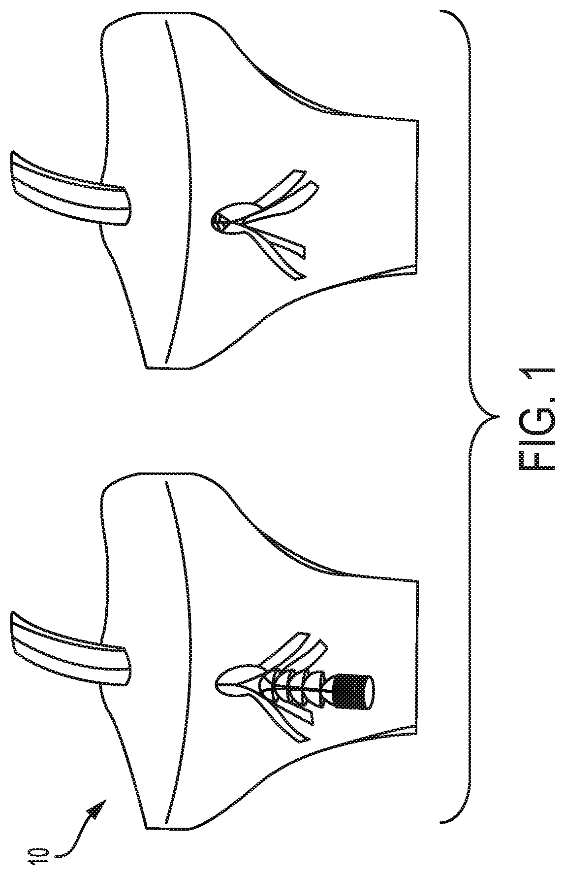
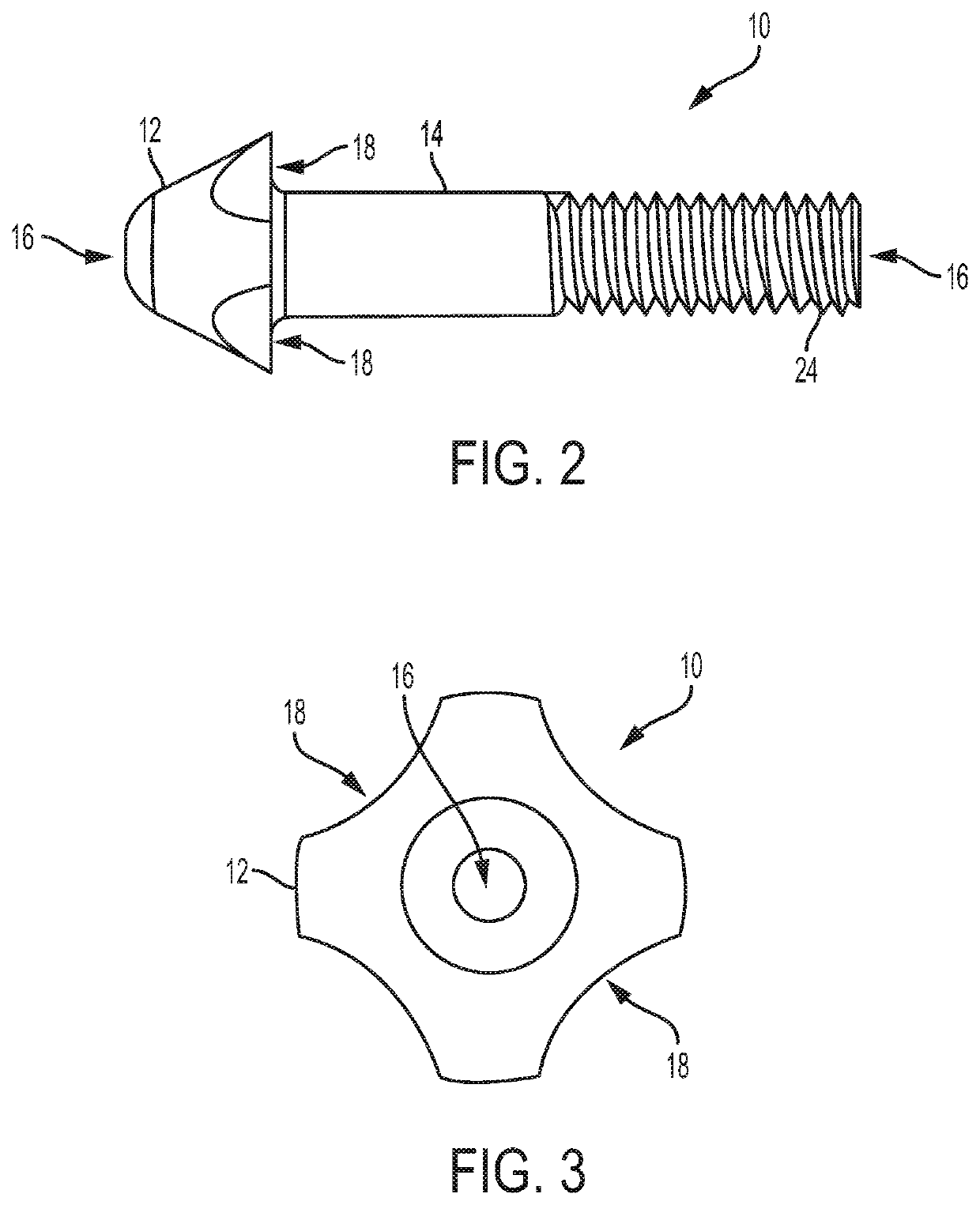
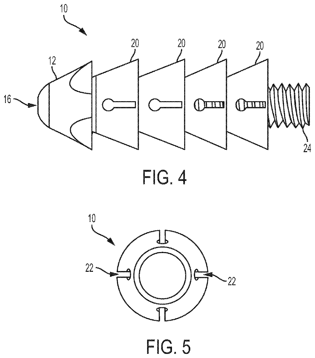
[0023]Referring to the figures, wherein like numeral refer to like parts throughout, there is seen in FIG. 1 an expanding anchor 10 according to the present invention for insertion into a bone tunnel during knee surgery and then deployment to retain a graft in the bone tunnel. Referring to FIGS. 2 and 3, anchor 10 comprises a head 12 that is generally conical fixed to a first end of a body 14 that is tubular. Body 14 is cannulated to have a through bore 16 to accept a guide wire or guide pin used to aid in placement of anchor 10 during a surgical operation. As seen in FIG. 3, head 12 may include one or more scallops 18 that can accommodate the limbs of a graft. The second end of body 14 includes exterior threads 24.

[0024]Referring to FIG. 4, a series of segments 20 that are generally frustroconical are slidingly positioned along body 14 and oriented so that the taper of segments 20 expand outwardly toward a second end of body 14 opposite from head 12. Segments 20 are capable of move...


PUM


Abstract

An anchoring system for a knee ligament reconstruction that can secure a graft within a bone tunnel. The anchor system includes an anchor having a tubular body extending along a longitudinal axis from a proximal end to a distal end. A conical head is fixed to the distal end of the tubular body. A series of expandable segments are positioned along the tubular body and moveable along the body into a compacted, deployed position where the segments expand radially to engage the inside of a bone tunnel. A threaded drive member may move the segments to the deployed configuration once the anchor and graft are positioned in the bone tunnel. A drive tool may be used to advance the drive member and can include a moveable shaft that pushes a strike plate out of the rear of the handle to provide an indication whether the anchor has been fully deployed.

Description

CROSS-REFERENCE TO RELATED APPLICATIONS[0001]The present application claims priority to U.S. Provisional No. 62 / 518,245, filed on Jun. 12, 2017.BACKGROUND OF THE INVENTION1. Field of the Invention[0002]The present invention relates to knee ligament reconstruction and, more particularly, to an expanding anchor that can be used as an interference fixing device in a knee ligament reconstruction.2. Description of the Related Art[0003]During knee ligament reconstructions, such anterior cruciate ligament surgery, a soft tissue graft often needs to be pulled into and secured in a bone tunnel. Conventional approaches to anchoring the graft involve the use of an interference screw or anchor that is inserted into the bone tunnel after the graft is pulled into place. Although this approach provides a strong anchor point, insertion of the screw or anchor is difficult and associated with high failure rates. Accordingly, there is a need for an implant that can more readily be used to compress a g...

Claims


Application Information

Patent Timeline
IPC IPC(8): A61F2/08
CPCA61F2002/0882A61F2250/001A61F2002/0835A61F2/0811A61F2230/0067A61F2002/0841A61F2/0805A61B17/0401A61B2017/0464A61B2017/0409
Inventor KAM, ANDREWMUSER, ANDREW P.
Owner CONMED CORP
Why Eureka
Try Eureka