Roller shade for non-rectangular windows

Active Publication Date: 2020-06-18
CRESTRON ELECTRONICS
View PDF0 Cites 2 Cited by
  • Summary
  • Abstract
  • Description
  • Claims
  • Application Information

AI Technical Summary

Benefits of technology

The patent describes a roller shade that can be installed in a non-rectangular structural opening. The shade is designed to cover the opening and is attached to the sides of the opening. It includes a roller tube, a shade material, and a shade drive unit. The shade material is attached to the roller tube and can be unrolled or rolled up. The shade also has a hem bar assembly with wheels that can be guided along the sides of the opening. The patent also describes a fascia to hide the tension modules and the roller tube from view. The technical effect of this invention is to provide a roller shade that can be easily installed in non-rectangular openings and provides effective coverage without compromising the appearance of the opening.

Problems solved by technology

The pair of side jambs of the non-rectangular structural opening may be unparalleled causing the pair of extendable arms to extend from or retract into the open ends of the hollow housing as the shade material is rolled on or unrolled from the roller tube.

Method used


Image

  • Roller shade for non-rectangular windows
  • Roller shade for non-rectangular windows
  • Roller shade for non-rectangular windows

Examples


Embodiment Construction

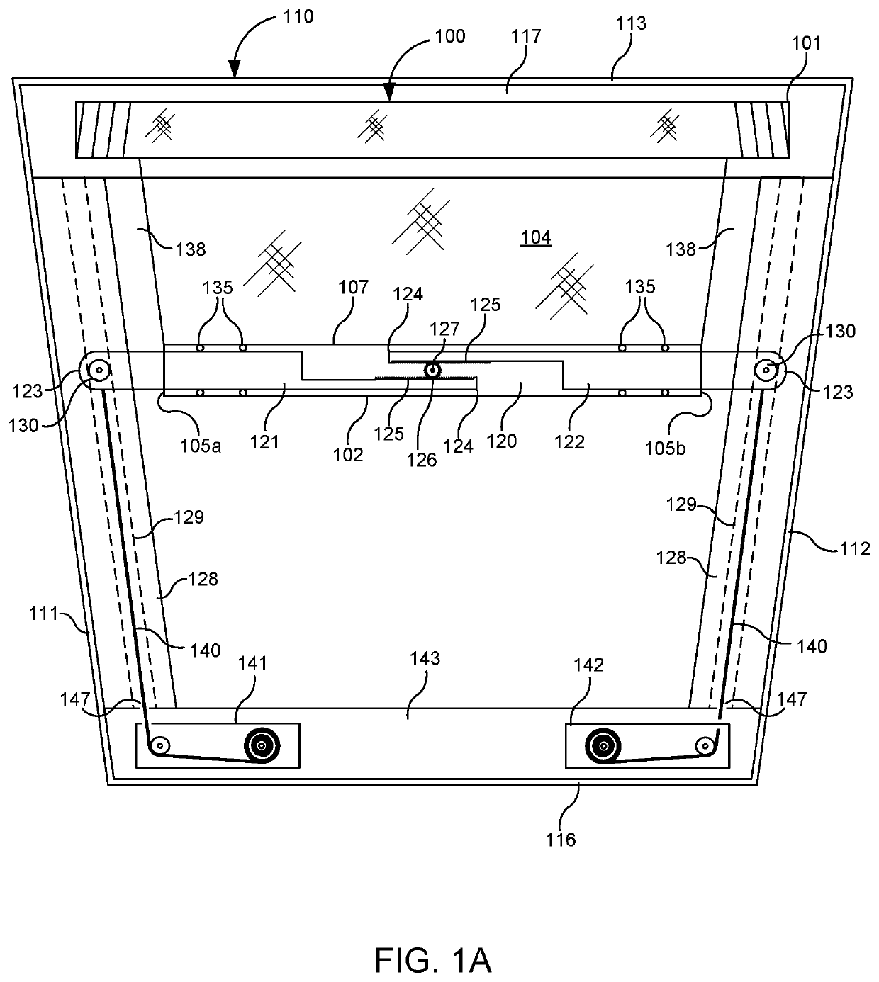
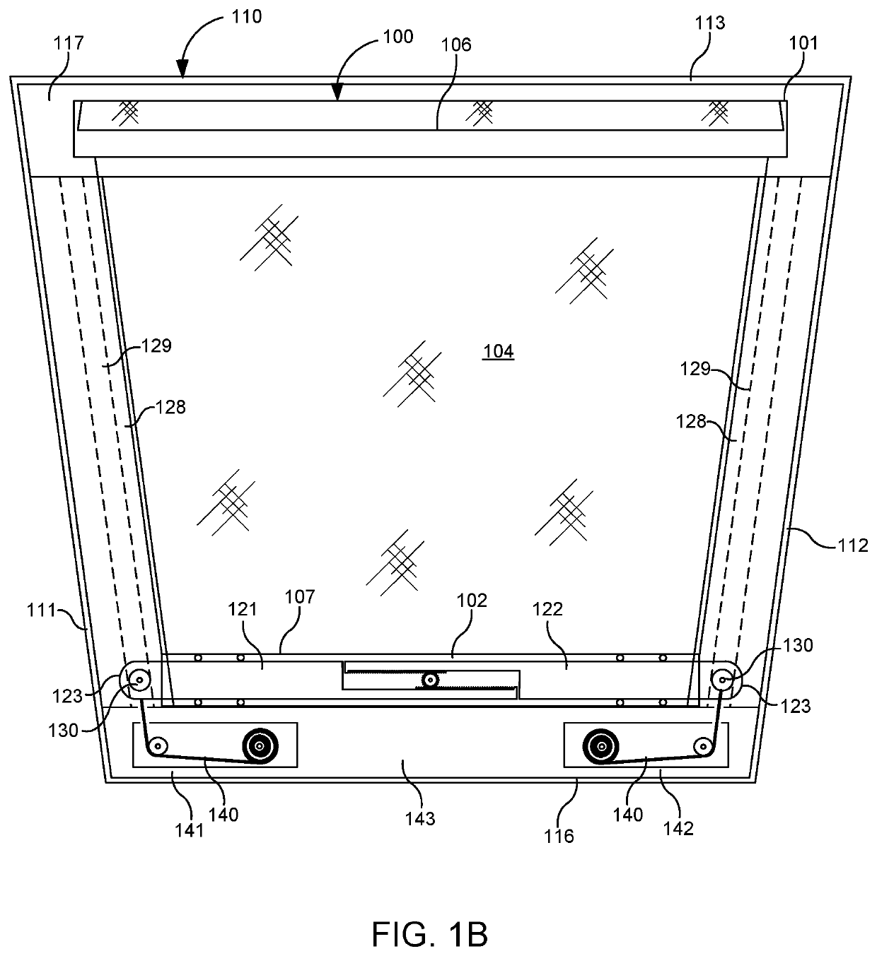
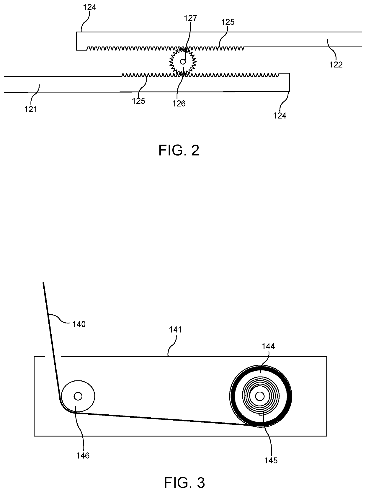
[0027]The embodiments are described more fully hereinafter with reference to the accompanying drawings, in which embodiments of the inventive concept are shown. In the drawings, the size and relative sizes of layers and regions may be exaggerated for clarity. Like numbers refer to like elements throughout. The embodiments may, however, be embodied in many different forms and should not be construed as limited to the embodiments set forth herein. Rather, these embodiments are provided so that this disclosure will be thorough and complete, and will fully convey the scope of the inventive concept to those skilled in the art. The scope of the embodiments is therefore defined by the appended claims. The detailed description that follows is written from the point of view of a control systems company, so it is to be understood that generally the concepts discussed herein are applicable to various subsystems and not limited to only a particular controlled device or class of devices.

[0028]Re...


PUM


Abstract

A roller shade adapted to be installed in a non-rectangular structural opening comprising a roller tube, a shade material, a hem bar, a shade drive unit adapted to rotate the roller tube, and a pair of longitudinal side channels adapted to be attached to the sides of the structural opening. The shade material comprises a shape that corresponds to the shape of the structural opening to substantially cover thereof. The hem bar may be extendable and may comprise a pair of wheels at its opposite terminal ends. Each wheel is adapted to be retained by and travel within one of the longitudinal channels which are adapted to guide the hem bar assembly along the side jambs and control an extension of the extendable hem bar as the shade material is rolled on or unrolled from the roller tube and the distance between the side jambs changes. The roller shade may further comprise a pair of tension modules adapted to be attached opposite from the roller tube. Each tension module comprises a retractable cable attached to the hem bar proximate to one of the wheels to provide tension on the hem bar assembly.

Description

BACKGROUND OF THE INVENTIONTechnical Field[0001]Aspects of the embodiments relate to shades, and more particularly to systems, methods, and modes for a roller shade for a non-rectangular window, such as trapezoidal, parallelogram, as well as other regular or irregular quadrilateral shaped windows, and which may be mounted in different orientations and tilt angles.Background Art[0002]Roller shades are effective in screening windows, doors, or the like, to achieve privacy and thermal effects. A roller shade typically includes a rectangular shade material, such as fabric, attached at its top end to a cylindrical rotating tube, called a roller tube, and at an opposite bottom end to a hem bar. The shade material is wrapped around the roller tube. The roller tube is rotated, either manually or via an electric motor, in a first direction to roll down the shade material to cover a window and in a second direction to roll up the shade material to uncover the window.[0003]While windows are ty...

Claims


Application Information

Patent Timeline
IPC IPC(8): E06B9/58E06B9/44
CPCE06B9/44E06B9/58E06B2009/583E06B2009/2494E06B9/42E06B9/581E06B9/60
Inventor CAMPAGNA, MICHAEL
Owner CRESTRON ELECTRONICS
Why Eureka
Try Eureka