Chemical Delivery Rates to Remove Carbon Deposits from the Internal Combustion Engine

a technology of carbon deposits and chemical delivery rates, which is applied in the direction of combustion-air/fuel-air treatment, non-fuel substance addition to fuel, charge feed systems, etc., can solve the problems of carbon deposits that are unwanted, the way to remove them from the engine continues to be a problem, and the method is time-consuming and expensiv

Active Publication Date: 2020-06-18
ATS CHEM LLC
View PDF0 Cites 1 Cited by
  • Summary
  • Abstract
  • Description
  • Claims
  • Application Information

AI Technical Summary

Benefits of technology

[0027]Additionally, it is an object of the invention to have such chemicals / chemical mixes run within the internal combustion engine during cleaning without heavy smoke, stalling the engine, or creating running problems for the engine.SUMMARY OF THE INVENTION
[0028]The present invention relates to, inter alia, the selection of chemicals, the development of chemical mixtures, and the use of such selected chemicals and developed mixtures in order to remove the various carbon deposits encountered within road vehicle internal combustion engines, regardless of engine type, carbon type, vehicle driving history, mileage, vehicle fuel(s) used, and engine oil(s) used. The present invention also relates to improved apparatus for effectively delivering chemicals / chemical mixtures to vehicle induction systems.
[0035]While positioning the nozzle after the throttle plate and timing the delivery of the aerosol with the inrush of air when the throttle plate is opening is preferred, it is not necessary so long as contact between the throttle plate and the aerosol is minimized so as not to adversely affect keeping the liquid droplets in the air stream moving through the induction system. This is not an issue where the aerosol is delivered after the throttle plate. Positioning the nozzle in front of the throttle plate has commercial advantages in the form of both reduced equipment and service personal costs. With this placement of the nozzle, the aerosol spray from the nozzle needs to be directed at the gap between the throttle plate and the throttle body when the throttle is in the closed position. (As those skilled in the design and maintenance of fuel delivery system understand, when the throttle plate is “closed” there is still some opening between the body and plate to provide air to the cylinders when the engine is idling.) This directing is optimized by the flattened nozzle tip of the present invention.

Problems solved by technology

Such carbon deposits have been unwanted since their discovery over one hundred years ago, and how to remove them from engines continues to be a problem today.
Obviously, an engine can be disassembled and manually cleaned, but this method is time consuming and expensive.
Additionally, chlorinated solvents are now not generally in use for environmental and safety reasons.
Additionally, as such amines are mixed into the fuel stock, they would not reach the induction system other than the direct intake valve area on GPI engines, or only the combustion chamber area on direct injected engines.
Further, independent of how injected into the cylinders, when standard consumer grades of gasoline are used the gasoline base is also a problem.
Also, the consumer grade gasoline base is a problem as it will flash into a vapor at the engine running temperatures.
This will not allow for a liquid base which is helpful to remove carbon deposits from the induction system and / or combustion chambers.
Additionally, Vataru's choosing a test engine that does not have carbon deposits contained within the engine acknowledges this teaching's inability to clean existing carbon deposits.
Furthermore, making assessments about cleaning efficacy based on improved mileage alone can be misleading because measured fuel mileage is primarily a measure of combustion efficiency rather than solely the cleanliness of the engine.
Again, this will not allow for a liquid base which is helpful to remove carbon deposits from the induction system.

Method used


Image

  • Chemical Delivery Rates to Remove Carbon Deposits from the Internal Combustion Engine
  • Chemical Delivery Rates to Remove Carbon Deposits from the Internal Combustion Engine
  • Chemical Delivery Rates to Remove Carbon Deposits from the Internal Combustion Engine

Examples


Embodiment Construction

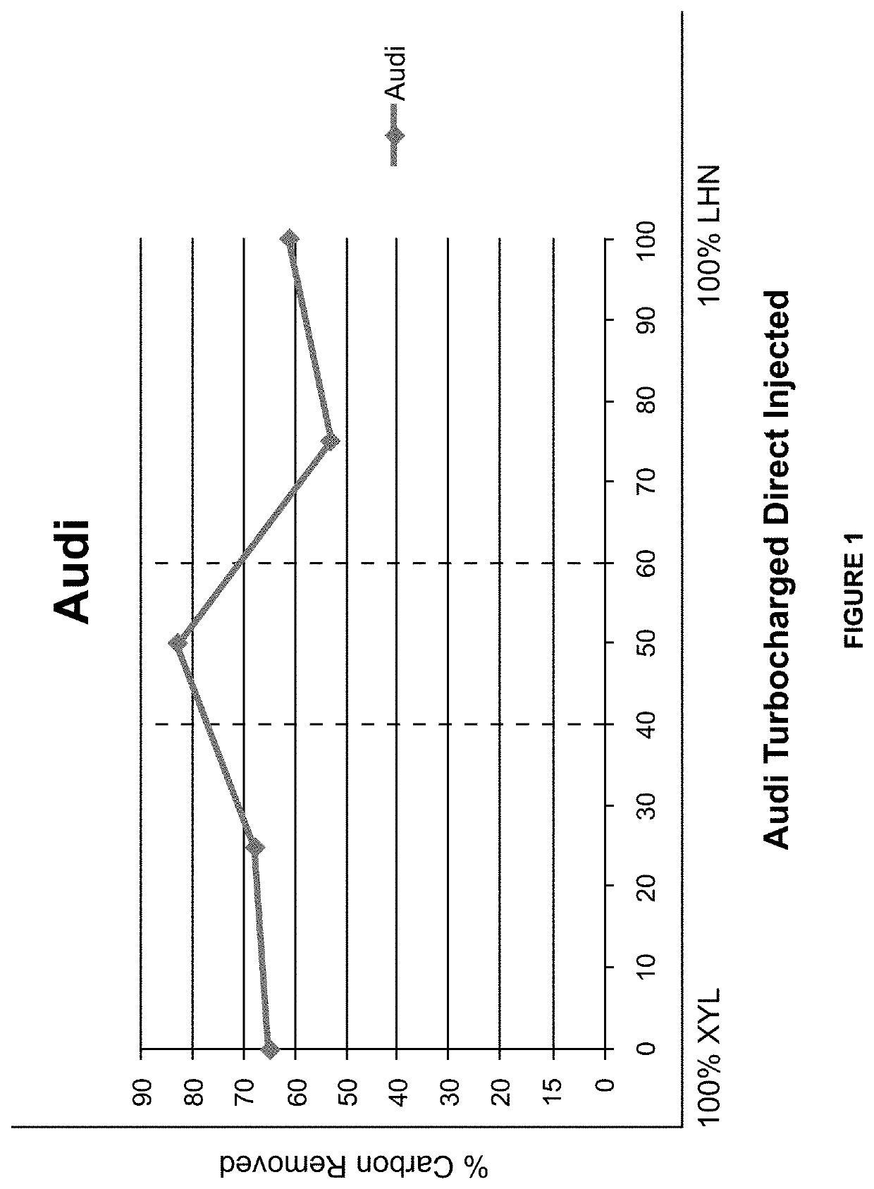
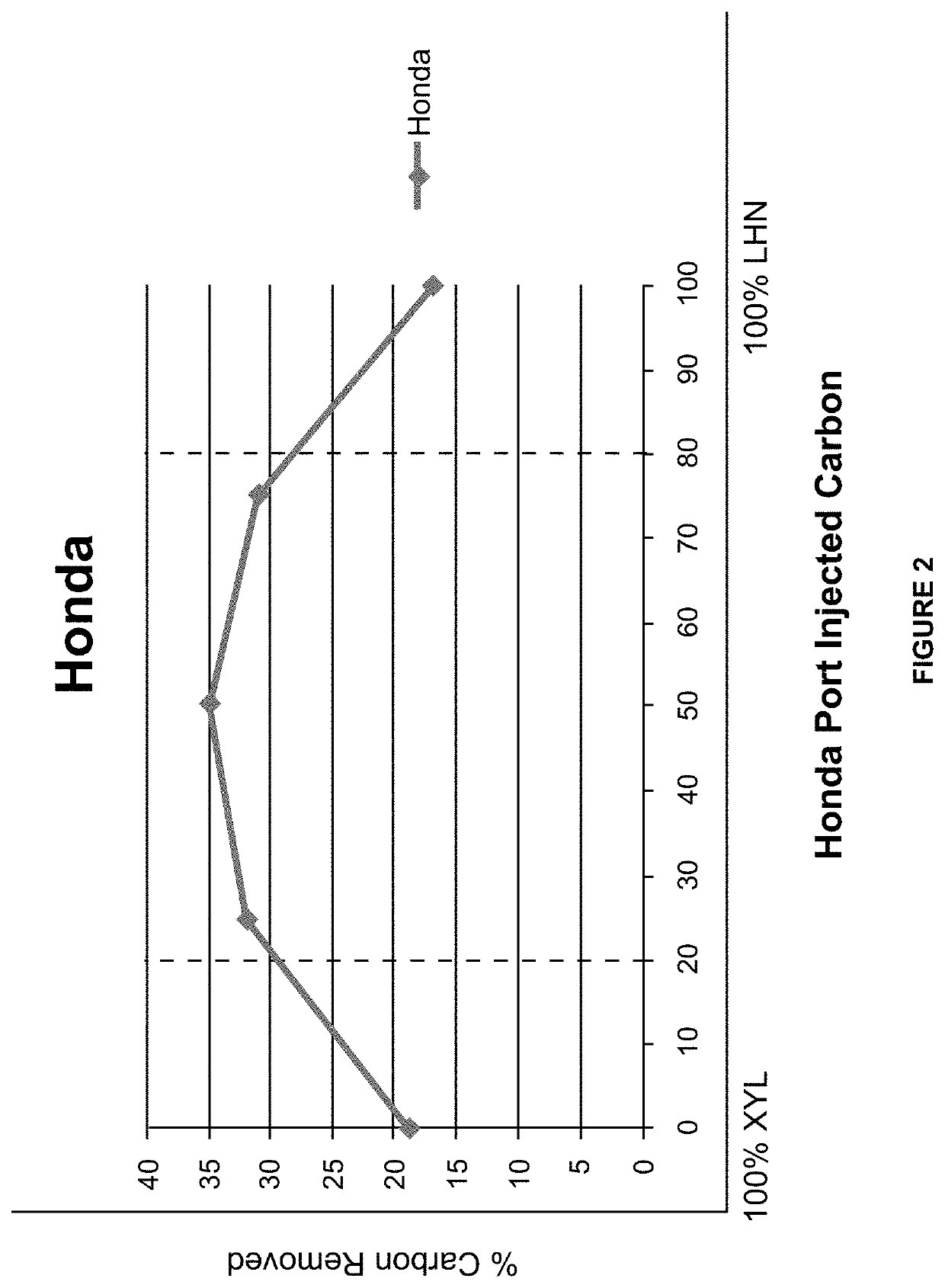
[0067]An in-depth understanding of carbon types and chemicals and chemical mixtures tested for their effectiveness in breaking down carbon accumulations is imperative in order to successfully remove these carbon deposits from road vehicle internal combustion engines. In order to accomplish this a testing procedure was developed including: (1) chemical and chemical mixture bench testing of road vehicle carbon (this is carbon that has been carefully removed by hand from the induction system and combustion chambers of road vehicle engines for the purpose of identifying and testing various carbon types and the effects of various chemicals and chemical mixtures on such various carbon types); and (2) testing the same types of carbon in running road vehicle engines with the same chemicals and chemical mixtures applied to the induction systems of such engines. In step (1) the carbon being tested is weighed both before and after the chemical (or chemical mixture) is applied, so that the amou...


PUM


Abstract

The present invention relates to the carbon deposit buildup in the internal combustion engine, or more specifically the removal of such carbon from the induction system, combustion chamber, and the exhaust system. The method is one in which a high volumetric flow rate of chemical / chemical mixes are used to remove a greater amount of carbon from the engine. These preferred chemical / chemical mix flow rates are 6 to 9 Gallons per hour, which is approximately 9 times the volumetric flow rate of the industry standard of 1 gallon per hour.

Description

[0001]This application is a continuation of and claims the priority of application Ser. No. 16 / 103,726, filed Aug. 14, 2018, which is a continuation-in-part of and claims the priority of: application Ser. No. 15 / 906,075, filed Feb. 27, 2018; application Ser. No. 15 / 704,644, filed Sep. 14, 2017; application Ser. No. 15 / 619,223, filed Jun. 9, 2017; application Ser. No. 15 / 617,966, filed Jun. 8, 2017; application Ser. No. 62 / 348,593, filed Jun. 10, 2016; application Ser. No. 62 / 458,414, filed Feb. 13, 2017; and application Ser. No. 62 / 471,817, filed Mar. 15, 2017.[0002]This application incorporates by reference the entirety of the following applications: Ser. No. 14 / 843,016 (herein the “'016 application”) filed Sep. 2, 2015 for “Dual Chemical Induction Cleaning Method and Apparatus for Chemical Delivery”; Ser. No. 14 / 584,684 (the “'684 application”) filed Dec. 29, 2014 also for “Dual Chemical Induction Cleaning Method and Apparatus for Chemical Delivery”; and Ser. No. 62 / 061,326 (the “...

Claims


Application Information

Patent Timeline
Patent Type & Authority Applications(United States)
IPC IPC(8): F02B77/04F02D19/12F02M35/10
CPCF02B77/04F02M35/10209F02D19/12F02M25/00
Inventor THOMPSON, BERNIE C.PEDERSON, NEAL R.THOMA, STEVEN G.
Owner ATS CHEM LLC
Why Eureka
Try Eureka