
Compositions for Engine Carbon Removal and Methods and Apparatus for Removing Carbon

a technology of carbon removal and combustion chambers, applied in the direction of machines/engines, combustion-air/fuel-air treatment, liquid cleaning, etc., can solve the problems of time-consuming and expensive methods, unwelcome carbon deposits, and inability to remove them from engines

Inactive Publication Date: 2020-08-27
ATS CHEM LLC
View PDF0 Cites 0 Cited by
  • Summary
  • Abstract
  • Description
  • Claims
  • Application Information

AI Technical Summary

Benefits of technology

The invention relates to the use of chemicals to remove carbon deposits in internal combustion engines. The chemicals are delivered without causing heavy smoke, stalling the engine, or running problems. The delivery is made through an improved apparatus that minimizes the impact on the air stream moving through the engine. The chemicals are directed at the gap between the throttle plate and the throttle body when the throttle is closed. The invention provides a more efficient and cost-effective way to keep engines running smoothly.

Problems solved by technology

Such carbon deposits have been unwanted since their discovery over one hundred years ago, and how to remove them from engines continues to be a problem today.
Obviously, an engine can be disassembled and manually cleaned, but this method is time consuming and expensive.
Additionally, chlorinated solvents are now not generally in use for environmental and safety reasons.
Additionally, as such amines are mixed into the fuel stock, they would not reach the induction system other than the direct intake valve area on GPI engines, or only the combustion chamber area on direct injected engines.
Further, independent of how injected into the cylinders, when standard consumer grades of gasoline are used the gasoline base is also a problem.
Also, the consumer grade gasoline base is a problem as it will flash into a vapor at the engine running temperatures.
This will not allow for a liquid base which is helpful to remove carbon deposits from the induction system and / or combustion chambers.
Additionally, Vataru's choosing a test engine that does not have carbon deposits contained within the engine acknowledges this teaching's inability to clean existing carbon deposits.
Furthermore, making assessments about cleaning efficacy based on improved mileage alone can be misleading because measured fuel mileage is primarily a measure of combustion efficiency rather than solely the cleanliness of the engine.
Again, this will not allow for a liquid base which is helpful to remove carbon deposits from the induction system.

Method used


Image

  • Compositions for Engine Carbon Removal and Methods and Apparatus for Removing Carbon
  • Compositions for Engine Carbon Removal and Methods and Apparatus for Removing Carbon
  • Compositions for Engine Carbon Removal and Methods and Apparatus for Removing Carbon

Examples


Embodiment Construction

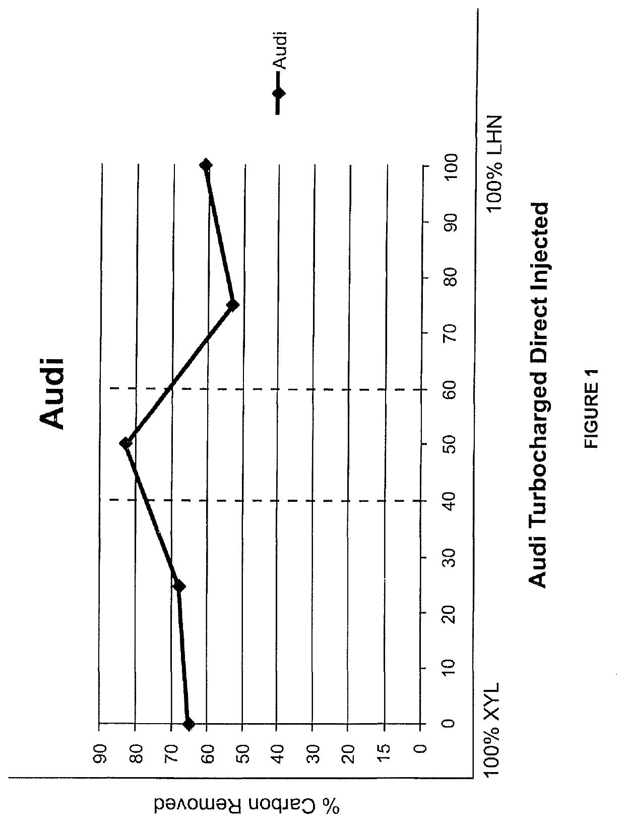
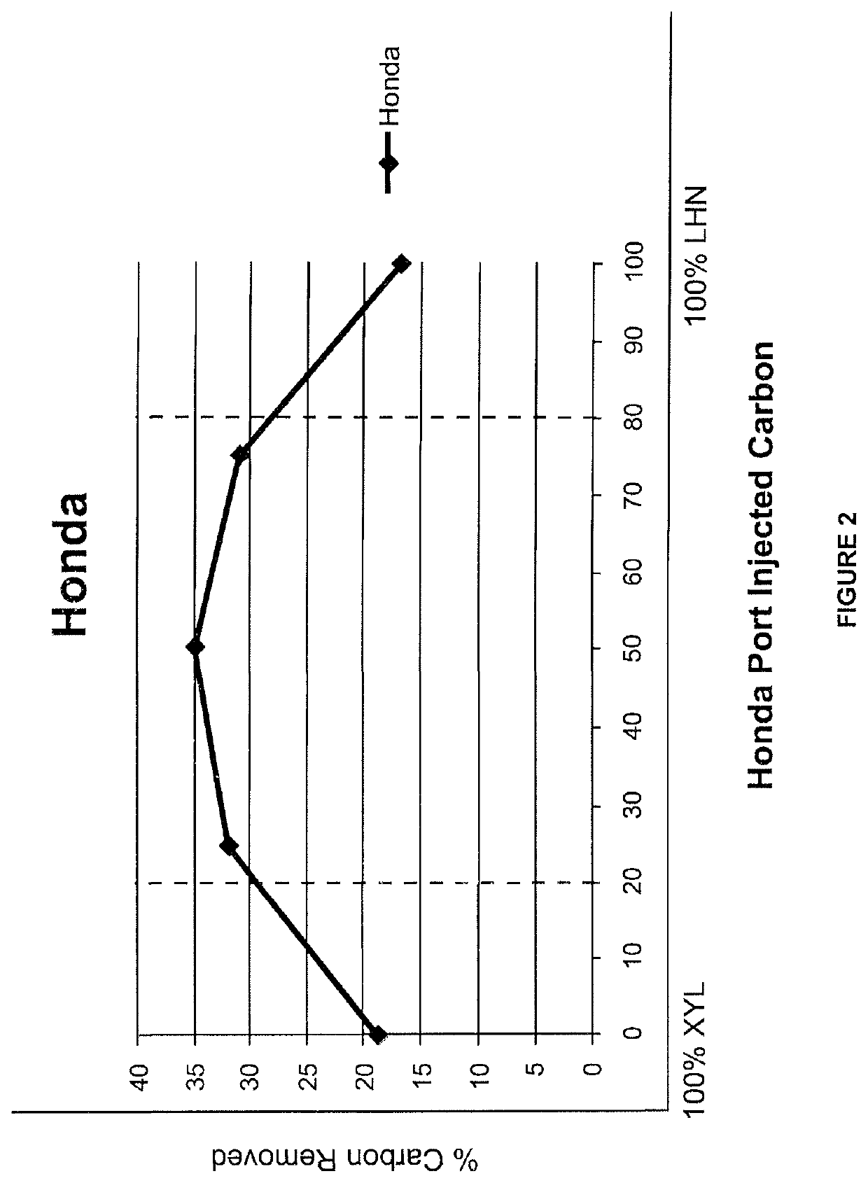
[0063]An in-depth understanding of carbon types and chemicals and chemical mixtures tested for their effectiveness in breaking down carbon accumulations is imperative in order to successfully remove these carbon deposits from road vehicle internal combustion engines. In order to accomplish this a testing procedure was developed including: (1) chemical and chemical mixture bench testing of road vehicle carbon (this is carbon that has been carefully removed by hand from the induction system and combustion chambers of road vehicle engines for the purpose of identifying and testing various carbon types and the effects of various chemicals and chemical mixtures on such various carbon types); and (2) testing the same types of carbon in running road vehicle engines with the same chemicals and chemical mixtures applied to the induction systems of such engines. In step (1) the carbon being tested is weighed both before and after the chemical (or chemical mixture) is applied, so that the amou...


PUM

PropertyMeasurementUnit
thicknessaaaaaaaaaa
thicknessaaaaaaaaaa
boiling pointaaaaaaaaaa

Abstract

This invention relates to cleaning the induction systems, the combustion chambers and exhaust systems of internal combustion engines. And, more particularly, to chemicals and mixtures of chemicals for removing the different types of carbon deposits encountered in internal combustion engines used in “road vehicles”. Carbon deposits were taken from the induction systems of these road vehicles for the purpose of bench testing such carbon and product development. More specifically, chemicals (i.e., solvents) and chemical mixes (i.e., solutions) have been accurately tested on such harvested carbon deposits for their ability to remove the various types of carbon deposits that accumulate within road vehicle internal combustion engines. Additionally this invention also relates to apparatus for delivering chemicals and chemical mixes. Which includes those developed by applicant, as well as those prior art products marketed for carbon removal, to the induction system of vehicles to maximize the effectiveness of the chemical delivery.

Description

[0001]This application is a divisional of application Ser. No. 15 / 619,223 filed Jun. 9, 2017, which is a continuation-in-part of: application Ser. No. 15 / 617,966, filed Jun. 8, 2017; Application Ser. No. 62 / 348,593, filed Jun. 10, 2016; Application Ser. No. 62 / 458,414, filed Feb. 13, 2017; and application Ser. No. 62 / 471,817, filed Mar. 15, 2017. The priority dates of these applications are all claimed.[0002]This application incorporates by reference the entirety of the following applications: Ser. No. 14 / 843,016 (herein the “'016 application”) filed Sep. 2, 2015 for “Dual Chemical Induction Cleaning Method and Apparatus for Chemical Delivery”; Ser. No. 14 / 584,684 (the “'684 application”) filed Dec. 29, 2014 also for “Dual Chemical Induction Cleaning Method and Apparatus for Chemical Delivery”; and Ser. No. 62 / 061,326 (the “'326 application”) filed Oct. 8, 2014. The '016 application is a continuation-in-part of application the '684 Application which, in turn, is a continuation-in-pa...

Claims


Application Information

Patent Timeline
Patent Type & Authority Applications(United States)
IPC IPC(8): F02B77/04F02M35/10B08B5/00B08B3/08C11D11/00
CPCB08B5/00B08B3/08F02B77/04C11D11/0041B08B2209/027F02M35/10209B08B2220/01C11D2111/20
Inventor THOMPSON, BERNIE C.THOMA, STEVEN G.
Owner ATS CHEM LLC
Learn More