
Display panel and display device

a display panel and display panel technology, applied in non-linear optics, instruments, optics, etc., can solve the problems of increased production costs, reduced notch area, and reduced notch area, so as to reduce the manufacturing cost of display panels and good light transmittance of notch areas

Inactive Publication Date: 2020-06-18
WUHAN CHINA STAR OPTOELECTRONICS TECH CO LTD
View PDF0 Cites 0 Cited by
  • Summary
  • Abstract
  • Description
  • Claims
  • Application Information

AI Technical Summary

Benefits of technology

The invention provides a new display panel and device that solved the problem of needing to cut off the notch area in existing full-screen display panels. By reducing the thickness of the light shielding film in the notch area, the panel has good light transmittance without needing to cut off the notch area. This reduces manufacturing costs and achieves a better light transmissive effect.

Problems solved by technology

A special-shaped cutting process is added in a process of cutting the display panel, which increases production costs.
That is, the existing full-screen display panels have a technical problem that the notch area needs to be cut.

Method used


Image

  • Display panel and display device
  • Display panel and display device
  • Display panel and display device

Examples


Embodiment Construction

[0037]The description of following embodiment, with reference to the accompanying drawings, is used to exemplify specific embodiments which may be carried out in the present disclosure. Directional terms mentioned in the present disclosure, such as “top”, “bottom”, “front”, “back”, “left”, “right”, “inside”, “outside”, “side”, etc., are only used with reference to the orientation of the accompanying drawings. Therefore, the used directional terms are intended to illustrate, but not to limit, the present disclosure. In the drawings, the components having similar structures are denoted by same numerals.

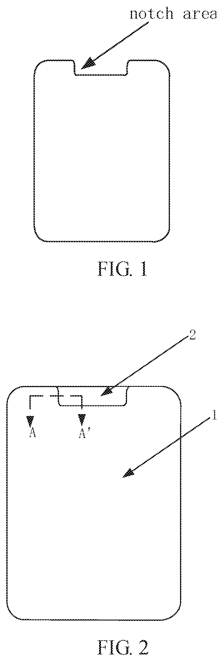
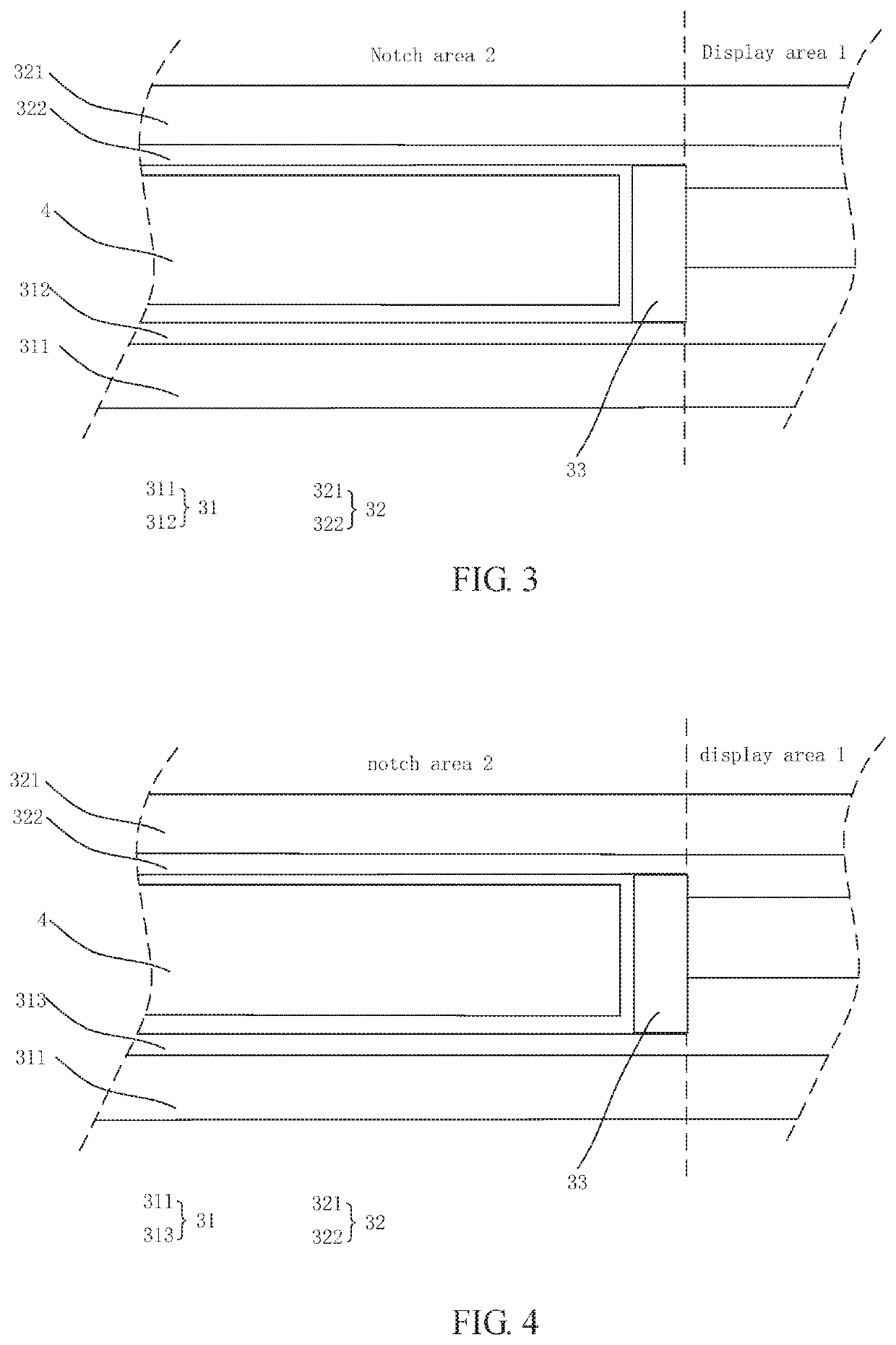
[0038]For a technology problem as shown in FIG. 1 that existing full-screen display panels need to cut a notch area off, the present disclosure as shown in FIG. 2 realizes a light transmissive effect of the notch area by reducing light shielding films in the notch area, so as to solve the technology problem.

[0039]In one embodiment as shown in FIG. 2, the present disclosure provides a di...


PUM

PropertyMeasurementUnit
areaaaaaaaaaaa
thicknessaaaaaaaaaa
transparentaaaaaaaaaa

Abstract

The present invention provides a display panel and a display device, including a display area and a notch area disposed at one side of the display area; a thickness of a light shielding film in the notch area is less than a thickness of a light shielding film in the display area. By reducing the thickness of the light shielding film in the notch area, good light transmittance of the notch area is kept. Based on this, the notch area does not need to be cut off, which solves the technical problem that the notch area needs to be cut off in the existing display panels.

Description

BACKGROUND OF INVENTIONField of Invention[0001]The present invention relates to a field of liquid crystal displays, and particularly to a display panel and a display device.Description of Prior Art[0002]With the development of display technology, full-screen technology with a high screen proportion, a large effective display area, and a better amazing display effect has gradually become mainstream. In order to achieve a full-screen display effect, conventional full-screen terminals need to avoid placing receivers and cameras in display screens, which will affect user experiences.[0003]In order to solve this problem, current technology uses special-shaped screen technology, which forms a notch by cutting a display panel, and then a receiver and a camera are placed in the notch.[0004]Referring to FIG. 1, existing full-screen display panel products usually use a special-shaped cutting method to cut material off a notch area of the display panel. A special-shaped cutting process is adde...

Claims


Application Information

Patent Timeline
Patent Type & Authority Applications(United States)
IPC IPC(8): G02F1/1335
CPCG02F1/133512G02F1/133514G02F2001/133357G02F1/133388G02F1/133357
Inventor YU, PENGFEI
Owner WUHAN CHINA STAR OPTOELECTRONICS TECH CO LTD
Learn More