
Liquid crystal display device and driving method thereof

a technology of liquid crystal display and driving method, which is applied in the direction of electric digital data processing, instruments, computing, etc., can solve the problem that the domain design fails to maintain the proper driving effect, and achieve the effect of increasing the cost of the devi

Inactive Publication Date: 2015-01-06
TCL CHINA STAR OPTOELECTRONICS TECH CO LTD
View PDF2 Cites 0 Cited by
  • Summary
  • Abstract
  • Description
  • Claims
  • Application Information

AI Technical Summary

Benefits of technology

This solution enables reverse scanning in LCD devices while maintaining the proper driving effect, similar to forward scanning, by adjusting the delay time and arranging scan lines to ensure the type 2 scan line is activated after the type 1 scan line, thus enhancing the display performance without additional costs.

Problems solved by technology

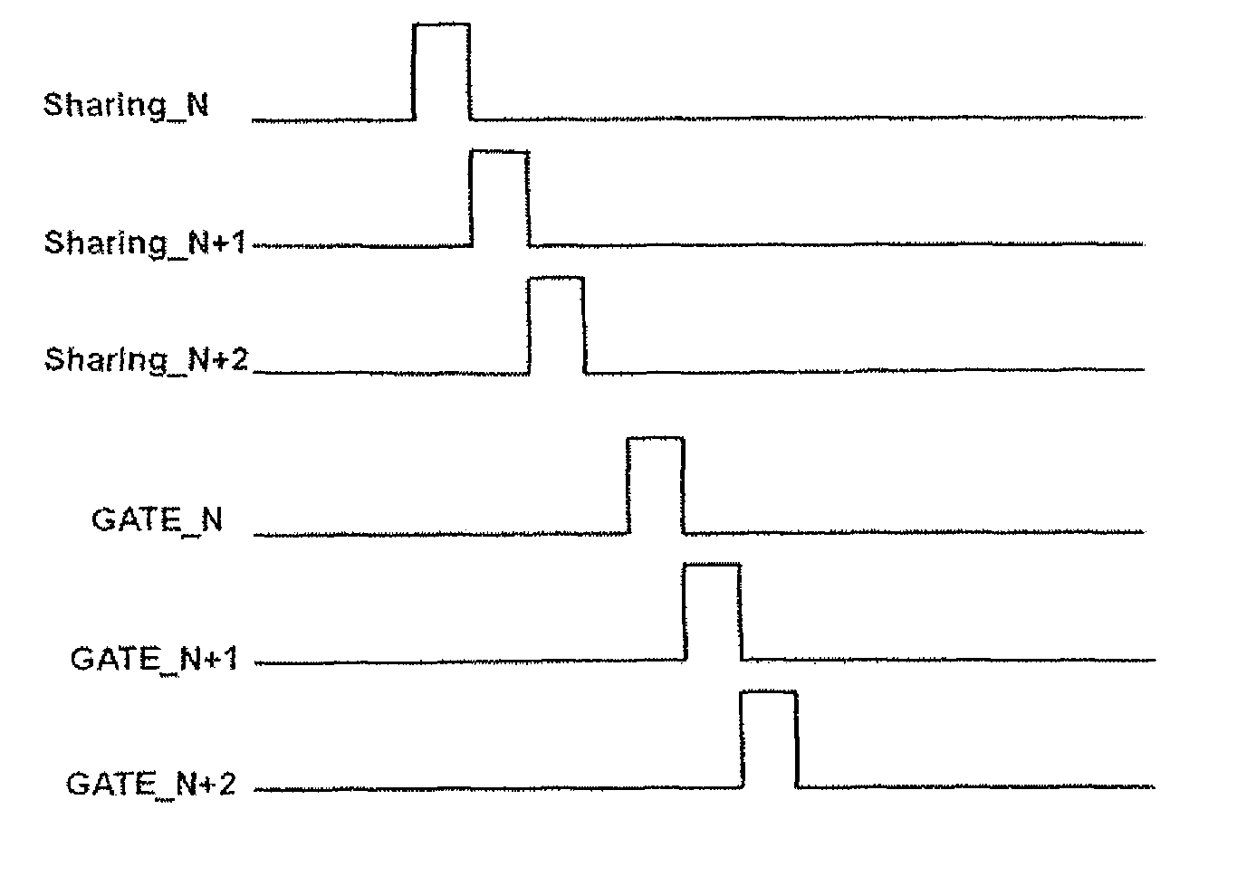
However, in such a design, when the display utilizes reverse scan driving, the driving waveform diagram for the scan lines is shown in FIG. 6, the time that the type 2 scan line is switched on is earlier than the time that the type 1 scan line is switched on, as a result, the LCD with the multi-domain design fails to maintain the proper driving effect.

Method used


Image

  • Liquid crystal display device and driving method thereof
  • Liquid crystal display device and driving method thereof
  • Liquid crystal display device and driving method thereof

Examples


Embodiment Construction

[0033]The following embodiments are referring to the accompanying drawings for exemplifying specific implementable embodiments of the present invention. Furthermore, directional terms described by the present invention, such as upper, lower, front, back, left, right, inner, outer, side and etc., are only directions by referring to the accompanying drawings, and thus the used directional terms are used to describe and understand the present invention, but the present invention is not limited thereto.

[0034]In the drawings, structure-like elements are labeled with like reference numerals.

[0035]In FIG. 7, which shows a structure schematic diagram showing scan lines and pixels of an LCD device of the present invention, the LCD device comprises a scan driving module 710, a data driving module (not shown in the drawing), pixels 720, data lines 730, shift register modules 740 and scan lines 750. The scan driving module 710 is used for generating a first scan signal. The data driving module ...


PUM


Abstract

The present invention involves in an LCD device, which comprises a scan driving module, a data driving module, pixels, data lines, shift register modules and scan lines, the scan lines include type 1 scan lines, each of which is connected with the scan driving module and the pixel for controlling charging time of the pixel according to a first scan signal and type 2 scan lines, each of which is connected with the shift register module and the pixel for controlling driving time for sub-pixels of the pixel. The present invention further involves in an LCD device driving method. The LCD device and the driving method of the present invention can realize reverse scanning without increasing device costs, thereby solving a technical problem that a current LCD device fails to maintain proper driving effects when utilizing reverse scan driving.

Description

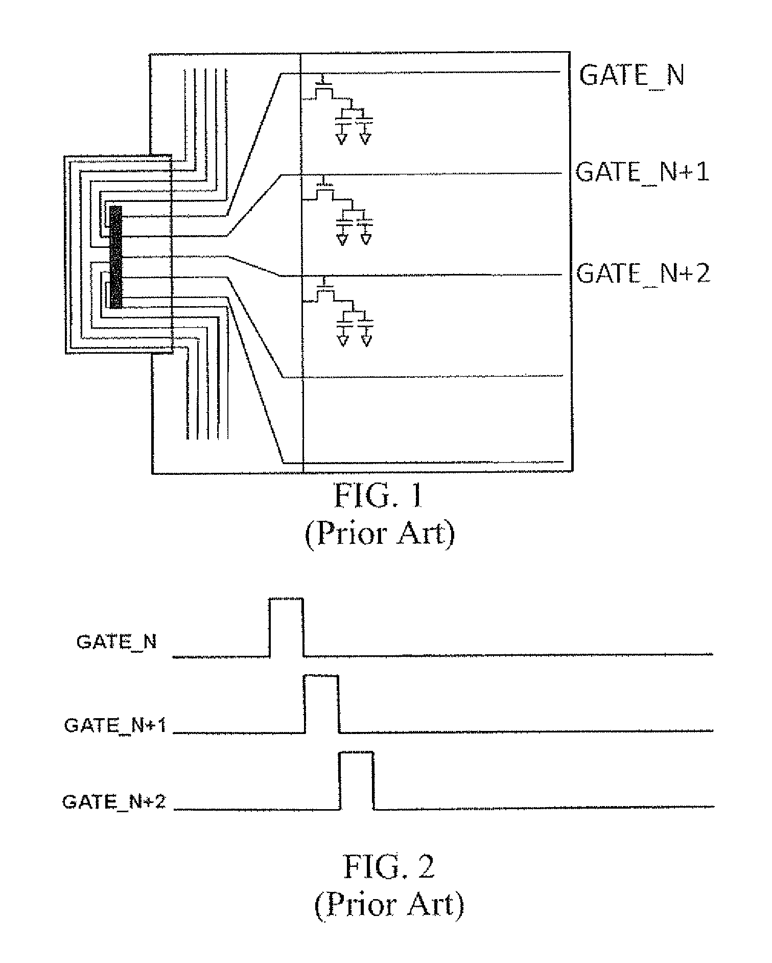
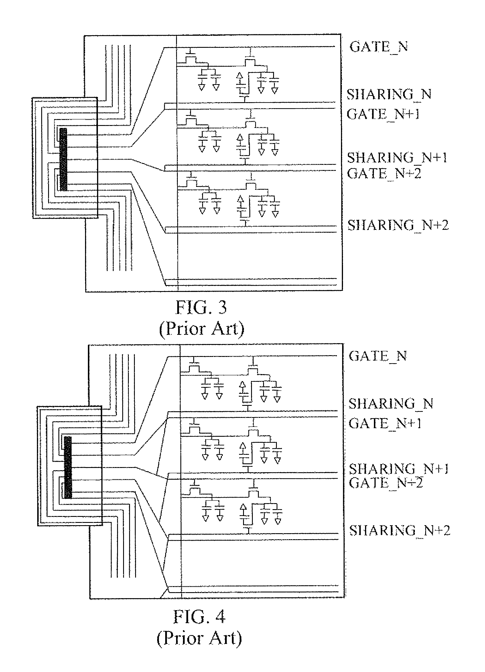
TECHNICAL FIELD OF THE INVENTION[0001]The present invention relates to a field of liquid crystal display (LCD), and more particularly, to an LCD device and a driving method thereof.BACKGROUND OF THE INVENTION[0002]A current LCD device generally utilizes a connection scheme between scan lines and pixels as shown in FIG. 1 to execute driving, FIG. 2 is a waveform diagram of driving signals for the scan lines shown in FIG. 1. As shown in FIG. 1, each pixel is connected to one scan line (e.g. GATE_N, GATE_N+1, GATE_N+2), the driving waveforms for the scan lines are shown in FIG. 2, the scan lines are switched on sequentially, a pulse width for each scan line is about 10-20 μs.[0003]When the LCD device has a multi-domain design, the connection scheme between the scan lines and pixels is shown in FIG. 3, each pixel in the drawing is connected to two scan lines, one of the scan lines, which is referred to as a type 1 scan line, e.g. GATE_N, GATE_N+1, GATE_N+2, controls a voltage for chargi...

Claims


Application Information

Patent Timeline
Patent Type & Authority Patents(United States)
IPC IPC(8): G09G3/36G09G5/02
CPCG09G3/3659G09G3/3677G09G2300/0426G09G2300/0443G09G2300/0814G09G2310/0251G09G2310/0283G09G2310/0286
Inventor ZHANG, XIN
Owner TCL CHINA STAR OPTOELECTRONICS TECH CO LTD
Learn More