Liquid ejecting head and liquid ejecting apparatus
a liquid ejecting and liquid technology, applied in printing and other directions, can solve problems such as defective printing and unstable discharge of ink
- Summary
- Abstract
- Description
- Claims
- Application Information
AI Technical Summary
Benefits of technology
Problems solved by technology
Method used
Image
Examples
embodiment
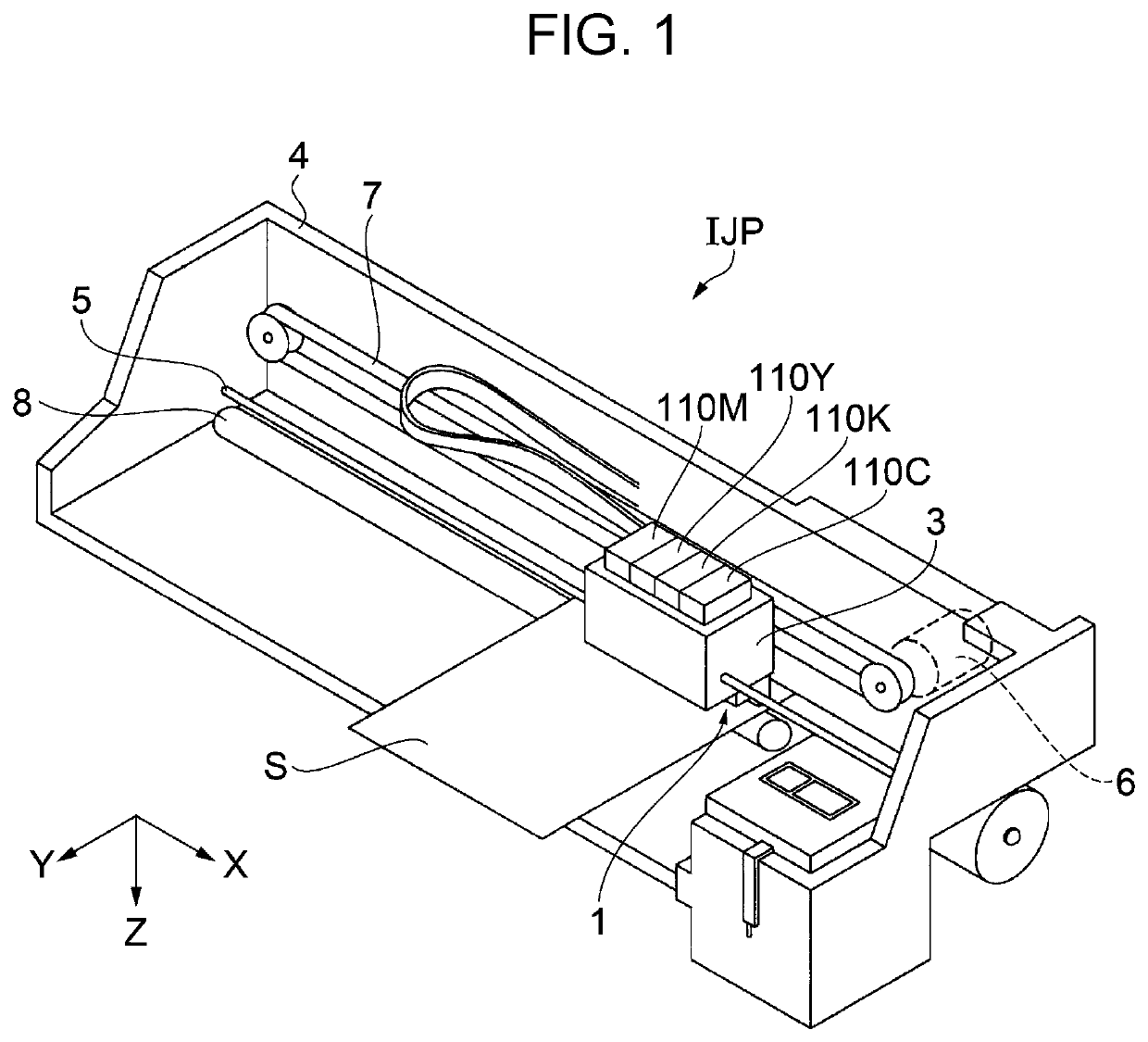
[0036]FIG. 1 is a perspective view of a liquid ejecting apparatus IJP according to the embodiment. First, a schematic configuration of the liquid ejecting apparatus IJP according to the present embodiment will be described with reference to FIG. 1.
[0037]In the following description, the width direction of the liquid ejecting apparatus IJP will be referred to as the X direction, the depth direction of the liquid ejecting apparatus IJP will be referred to as the Y direction, and the height direction of the liquid ejecting apparatus IJP will be referred to as the Z direction. The X direction and the Y direction are directions along a horizontal plane. The Z direction is a gravity direction orthogonal to the horizontal plane. Further, the distal end sides of direction-indicating arrows will be defined as +directions and the proximal end sides of the direction-indicating arrows will be defined as -directions. Although the directions (X, Y, and Z) are mutually orthogonal in the present em...
modification example 1
[0194]FIG. 10, which corresponds to FIG. 9, is a sectional view of the main portion of the head main body 2 of Modification Example 1.
[0195]In the embodiment, each common flow path 100 is provided with one compliance portion 49. In the present modification example, the common flow path 100Y of the nozzle row set 23Y having the long inter-nozzle row distance N is provided with a new compliance portion 62 as well as the compliance portion 49Y. The compliance portion 62 is provided on the top surface of the common flow path 100Y.
[0196]This is the main difference between the present modification example and the embodiment.
[0197]Hereinafter, the head main body 2 according to the present modification example will be described with reference to FIG. 10. The following description will focus on the difference from the embodiment. Components identical to those of the embodiment will be denoted by the same reference numerals and redundant description will be omitted.
[0198]As illustrated in FIG...
modification example 2
[0202]FIG. 11, which corresponds to FIG. 9, is a sectional view of the main portion of the head main body 2 of Modification Example 2.
[0203]In the embodiment described above, each common flow path 100 is provided with one compliance portion 49. In the present modification example, the common flow path 100Y of the nozzle row set 23Y having the long inter-nozzle row distance N is provided with a new compliance portion 66 as well as the compliance portion 49Y. The compliance portion 66 is provided on the side surface of the common flow path 100Y.
[0204]This is the main difference between the present modification example and the embodiment.
[0205]Hereinafter, the head main body 2 according to the present modification example will be described with reference to FIG. 11. The following description will focus on the difference from the embodiment. Components identical to those of the embodiment will be denoted by the same reference numerals and redundant description will be omitted.
[0206]In t...
PUM
 Abstract
Description
Claims
Application Information
 - R&D
- Intellectual Property
- Life Sciences
- Materials
- Tech Scout
- Unparalleled Data Quality
- Higher Quality Content
- 60% Fewer Hallucinations
Browse by: Latest US Patents, China's latest patents, Technical Efficacy Thesaurus, Application Domain, Technology Topic, Popular Technical Reports.
© 2025 PatSnap. All rights reserved.Legal|Privacy policy|Modern Slavery Act Transparency Statement|Sitemap|About US| Contact US: help@patsnap.com


