Lower tool with friction reduction device

A tool and friction coefficient technology, applied in the field of lower tools, can solve problems such as heavy technical work and increased production costs, and achieve the effects of improving safety, long use intervals, and avoiding jamming

Active Publication Date: 2020-12-11
TRUMPF MASCHEN AUSTRIA
View PDF9 Cites 0 Cited by
  • Summary
  • Abstract
  • Description
  • Claims
  • Application Information

AI Technical Summary

Problems solved by technology

The realization of such a concept requires relatively heavy technical work, which leads to increased production costs

Method used


Image

  • Lower tool with friction reduction device
  • Lower tool with friction reduction device
  • Lower tool with friction reduction device

Examples


Embodiment Construction

[0045] First of all, it should be noted that in the different embodiments described, the same parts have the same reference numerals and / or the same component names, wherein the disclosure contained in the entire specification can be similarly interchanged to have the same components. on the same parts with the same reference numerals and / or the same component names. Furthermore, selected position descriptions in the description (eg at top, at bottom, on the side) refer to the directly described and depicted view, and in the event of a change of position these position descriptions should be similarly replaced by the new position.

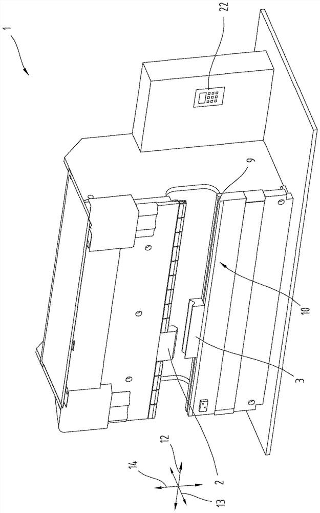
[0046] exist figure 1 , a schematic representation of a bending machine 1 with a system controller 22 , an upper tool 2 and a lower tool 3 arranged on a tool holder 10 is shown. The schematic illustration also shows a substantially vertical load direction 14 and a longitudinal direction 12 along which the lower tool 3 is displaceable in the guide ...


PUM

PropertyMeasurementUnit
friction coefficientaaaaaaaaaa

Abstract

The invention relates to a lower tool (3) for a bending machine (1), in particular a die bending machine, comprising a longitudinally extending main body (5) which, on its underside (6), has a tool shaft (8) for receiving in a guide groove (9) of a tool holder (10) and optionally in the transverse direction (13), tool shoulders (7), and at least one friction reduction device (11) is arranged on the underside (6) of the main body (5) in order to reduce a friction force (15) between the underside (6) and the tool holder (10) during a displacement of the lower tool (3) in the longitudinal direction (12), characterized in that the at least one friction reduction device (11) is designed in such a way that a weight force (17) of the lower tool (3) on the tool holder (10), under the application of a pretensioning force (16) in the direction of the weight force (17), causes a resultant normal force (18) of the lower tool (3) on the tool receptacle (10) which is lower relative to the weight force (17).

Description

technical field [0001] The invention relates to a lower tool for a bending machine, in particular a die bending machine, comprising at least one friction reducing device for reducing the friction between the bottom side of the lower tool and the tool holder. Background technique [0002] In modern forming machines, especially in bending machines, it is often necessary to perform tool changes of the upper tool and / or lower tool. During this process, the forming and / or bending tools are optimally aligned with one another for the respective forming operation on the tool holder of the bending machine and can optionally be fixed and / or clamped during the bending operation to avoid accidents displacement. Here, especially with regard to the lower tools, simple tool changing systems that allow easy replacement are becoming more and more important. The lower tool usually has a longitudinally extending base body with a mold on its upper side which is designed for the respective for...

Claims


Application Information

Patent Timeline
Patent Type & Authority Applications(China)
IPC IPC(8): B21D5/02B21D37/14B21D5/04
CPCB21D5/0209B21D5/0236B21D5/0254B21D37/14B21D5/0227B21D5/04
Inventor 卡尔·巴德格鲁贝尔阿尔弗雷德·哈泽尔伯克海因茨·洛伊穆勒卡比尔·塞奇博维克
Owner TRUMPF MASCHEN AUSTRIA
Why Eureka
Try Eureka