
Liquefied natural gas filling device

a technology for liquefied natural gas and filling devices, which is applied in the direction of container filling under pressure, electrical generators, vessel construction details, etc., to achieve the effect of maintaining the handleability of the setting panel, preventing the breakage of the hose and preventing the leakage of lng and natural gas, and connecting the range of the filling hos

Active Publication Date: 2018-07-03
TOKYO TATSUNO CO LTD
View PDF16 Cites 0 Cited by
  • Summary
  • Abstract
  • Description
  • Claims
  • Application Information

AI Technical Summary

Benefits of technology

[0011]Then, the object of the present invention is to provide an LNG filling apparatus for safely filling LNG in LNG vehicles.
[0013]With the present invention, after natural gas in an in-vehicle tank is recovered, LNG can be filled in the in-vehicle tank. A single hose is used for the recovery and the filling, so that tangle of hoses does not occur. With this, breakage of the hose and leakages of LNG and natural gas can be prevented, and LNG can be safely filled in the in-vehicle tank. And, the gloves mounting part can prevent the operator from forgetting to wear the gloves.
[0014]In addition, an LNG filling apparatus for filling LNG in an in-vehicle tank of the present invention is characterized by having a housing; a recovery hose and a filling hose separately led from the housing; a recovery mechanism for recovering natural gas from the in-vehicle tank via the recovery hose; a filling mechanism for filling LNG in the in-vehicle tank via the filling hose; and a gloves mounting part on which gloves used by an operator of the liquefied natural gas filling apparatus are mounted and which prevents a filling nozzle at an end of the filling hose from being detached in case that the gloves are put on the gloves mounting part. With the present invention, after natural gas in an in-vehicle tank is recovered via the recovery hose, LNG can be filled in the in-vehicle tank via the filling hose, and the recovery and the filling can be performed by the exclusive hoses separately led from the recovery mechanism and the filling mechanism. And, the gloves mounting part can prevent the operator from forgetting to wear the gloves.
[0016]In the above LNG filling apparatus, a backing plate for preventing droplets from falling below a filling pipe in the housing can be mounted. With this, in case that an interval between fillings is long, it is prevented that a pipe and the like positioned on a lower part in the housing become eroded by dropped water that is generated by melting frost attached to the filling pipe, and safety filling of LNG can be continued for a long period of time.
[0017]Further, the liquefied natural gas filling apparatus may further comprise: a ground wire for releasing electricity that is charged on the liquefied natural gas filling apparatus to an outside thereof to prevent generation of spark; and an air hose for removing dusts or / and frosts attached to the nozzle at the end of the hose or the filling nozzle at the end of the filling hose, wherein the ground wire and the air hose can be separately reeled on reels of automatic reeling type. With this, the ground wire and the air hose can be prevented from being intertwined with each other or with the hose, which prevents breakages of the ground wire, the air hose and the hose and leakages of LNG and natural gas due to their breakages.
[0018]As described above, with the present invention, it becomes possible to safely fill LNG in LNG vehicles.

Problems solved by technology

In addition, infrastructures for supplying LNG are not built, and LNG vehicles do not become common in Japan, so that it is necessary to take care of users who are unfamiliar with filling LNG.

Method used


Image

  • Liquefied natural gas filling device
  • Liquefied natural gas filling device
  • Liquefied natural gas filling device

Examples


Embodiment Construction

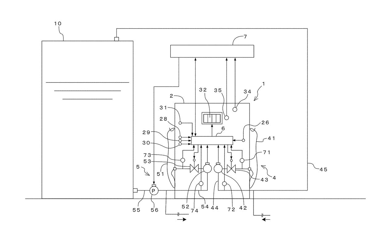
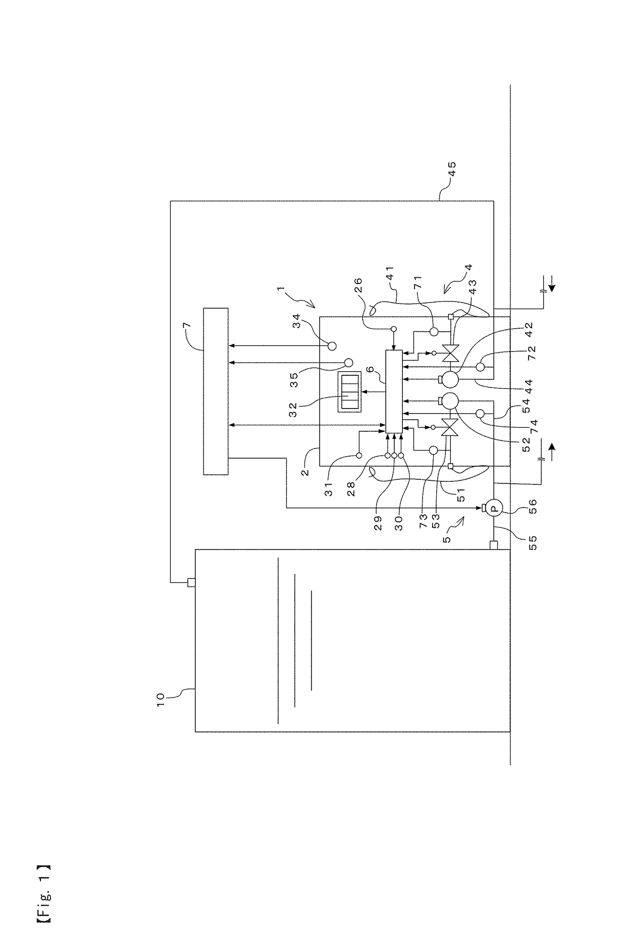
[0027]FIG. 1 shows an example of a filling facility having an LNG filling apparatus according to the present invention, and the filling facility is provided with a filling apparatus 1, an LNG storage tank 10, a central control board 7 and others.

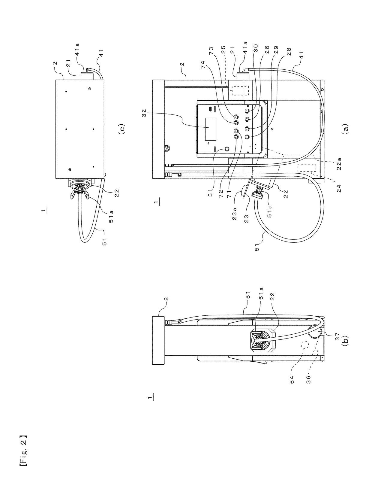
[0028]The filling apparatus 1 is, as shown in FIGS. 1 and 2, provided with a housing 2, a recovery mechanism 4 for recovering vaporized natural gas from an LNG in an in-vehicle tank, a filling mechanism 5 for filling an LNG stored in the LNG storage tank 10 to the in-vehicle tank, and a control device 6, installed in the housing 2, for controlling the whole filling apparatus 1.

[0029]The recovery mechanism 4 is provided with a recovery hose 41, led from the housing 2, having a connector 41a at a tip thereof, a pipe 44 for recovery, connected to the recovery hose 41, with a flowmeter 42 and a recovery valve 43, and a pipe 45 for connecting the pipe 44 to an upper portion of the LNG storage tank 10. The flowmeter 42 is installed to measure an a...


PUM


Abstract

An LNG filling apparatus that can safely fill LNG in LNG vehicles. A filling apparatus 1 for filling LNG in an in-vehicle tank, the apparatus 1 having a housing 2, a recovery hose 41 and a filling hose 51 separately led from the housing, a recovery mechanism 4 for recovering a natural gas from the in-vehicle tank via the recovery hose, and a filling mechanism 5 for filling LNG to the in-vehicle tank via the filling hose. Separately leading the recovery hose and the filling hose from the housing with these hoses in close proximity to each other allows a range capable of filling that is the overlap range between a connectable range of the recovery hose and a connectable range of the filling hose to be enlarged. A single hose led from the housing can be used for both of the recovery of the natural gas and the filling of the LNG, which prevents tangle of hoses with each other, and enables to fill the LNG in the in-vehicle tank safely.

Description

STATEMENT RE: FEDERALLY SPONSORED RESEARCH / DEVELOPMENT[0001]Not ApplicableCROSS-REFERENCE TO RELATED APPLICATIONS[0002]The present application claims priority to International Application No. PCT / JP2015 / 060116 filed on Mar. 31, 2015, which claims priority to Japanese Patent Application No. 2014-077737 filed Apr. 4, 2014.BACKGROUND[0003]1. Technical Field[0004]The present invention relates to an apparatus for filling liquefied natural gas in a tank mounted on a vehicle.[0005]2. Background Art[0006]Due to recent soaring crude oil prices, developments regarding natural gas vehicles, fuel-cell-powered vehicles and the like that run on liquefied natural gas (hereinafter abbreviated as “LNG”), compressed natural gas (CNG), hydrogen and the like as alternatives to petroleum are actively advanced. With this, infrastructures for supplying fuel to the above vehicles etc. have been built, and the present applicant proposed an apparatus for effectively filling hydrogen fuel in an in-vehicle tan...

Claims


Application Information

Patent Timeline
Patent Type & Authority Patents(United States)
IPC IPC(8): F17C5/02
CPCF17C5/02F17C2270/0184F17C2201/058F17C2205/037F17C2205/0335F17C2205/0364F17C2221/012F17C2221/033F17C2223/0161F17C2223/033F17C2225/0161F17C2225/033F17C2227/0135F17C2250/043F17C2250/075F17C2265/065F17C2270/0168F17C2201/056Y02E60/32
Inventor TAKAHASHI, KAZUSHIKOIKE, TSUYOSHIOZEKI, TAKESHI
Owner TOKYO TATSUNO CO LTD
Learn More