
Needle with closure and method

a technology of needles and closures, applied in the field of needles, can solve the problems of contaminating the ambient atmosphere of the needle, affecting the safety of the needle, and the fluid contained in the needle, so as to reduce the control of the environment of the needle, prevent the contamination of the needle port and interior, and prevent the contamination of the fluid flowing.

Pending Publication Date: 2022-07-14
DR PY INST LLC
View PDF0 Cites 0 Cited by
  • Summary
  • Abstract
  • Description
  • Claims
  • Application Information

AI Technical Summary

Benefits of technology

[0020]One advantage of the present invention is that the closure closes the needle port(s) with respect to ambient atmosphere thereby preventing contamination of the needle port and interior of the needle and, in turn, preventing contamination of fluid flowing therethrough. Another advantage of certain embodiments is that they allow sterile filling within a non-aseptic, non-sterile or relatively low SAL environment (e.g., about log 3 or lower) while nevertheless sterile filling fluids into containers or devices and hermetically resealing them. Accordingly, the filling of a non-preserved or preservative-free formulation with a self-closing filling needle of the present invention without control of the filling needle environment, or with reduced needle environment controls, can be safer than filling a preserved formulation in an aseptically-controlled environment with prior art filling apparatus and methods. Yet another advantage of some embodiments is that the closure is interposed between the needle port and a septum to prevent contact between the needle port and septum, and thereby further prevent any contamination of the needle port and interior of the needle and of any fluid flowing therethrough. In some embodiments, the combination of the self-closing needle, such as the needle with “sliding shutter” closure, and a liquid silicone drop (“LSD”) or other resealable septum, creates a unique system and method allowing for the reduction or elimination of environmental controls required by prior art sterile filling systems and methods, thereby allowing for a simplification in equipment, a reduction in the time associated with setup and operation of the equipment, and / or a reduction in the cost of equipment and / or aseptic filling and processing. As a consequence, devices and methods of the invention facilitate the ability of manufacturers of any size, including small entity manufacturers, to safely fill preserved or preservative-free formulations into aseptic environments, and to do so at a lower cost, with improved efficiency and / or in less time, than required by prior art aseptic filling devices and methods.

Problems solved by technology

One drawback encountered with prior art filling needles is that the interior of the needle, and any fluid contained therein, is exposed to the ambient atmosphere through the open fluid ports.
Even though the needle ports or eyes are very small, the incidence of contamination in aseptic filling is such that there still can be a need to control the environment in prior art filling machines in order to protect the filling needles, and particularly the end opening(s) of the filling needles, regardless of type.
If the ambient atmosphere is contaminated, the open ports can allow the interior of the needle and any fluid passing therethrough to become contaminated.
On the other hand, if the needle is used to dispense a contaminated fluid, or a fluid that might be harmful if it is exposed to or comes into contact with a person, the open ports can allow such fluid to contaminate its ambient atmosphere or potentially harm a person that contacts the needle or is in the vicinity thereof.
But, if for whatever reason, the latter were to be contaminated, a risk of contaminating the product inside the vial would exist.

Method used


Image

  • Needle with closure and method
  • Needle with closure and method

Examples


Embodiment Construction

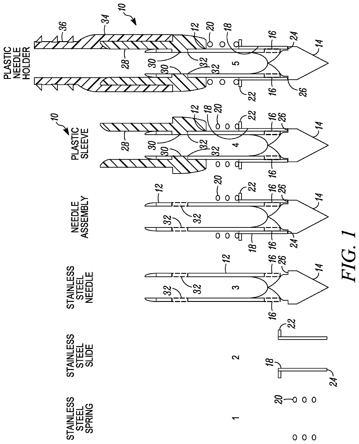
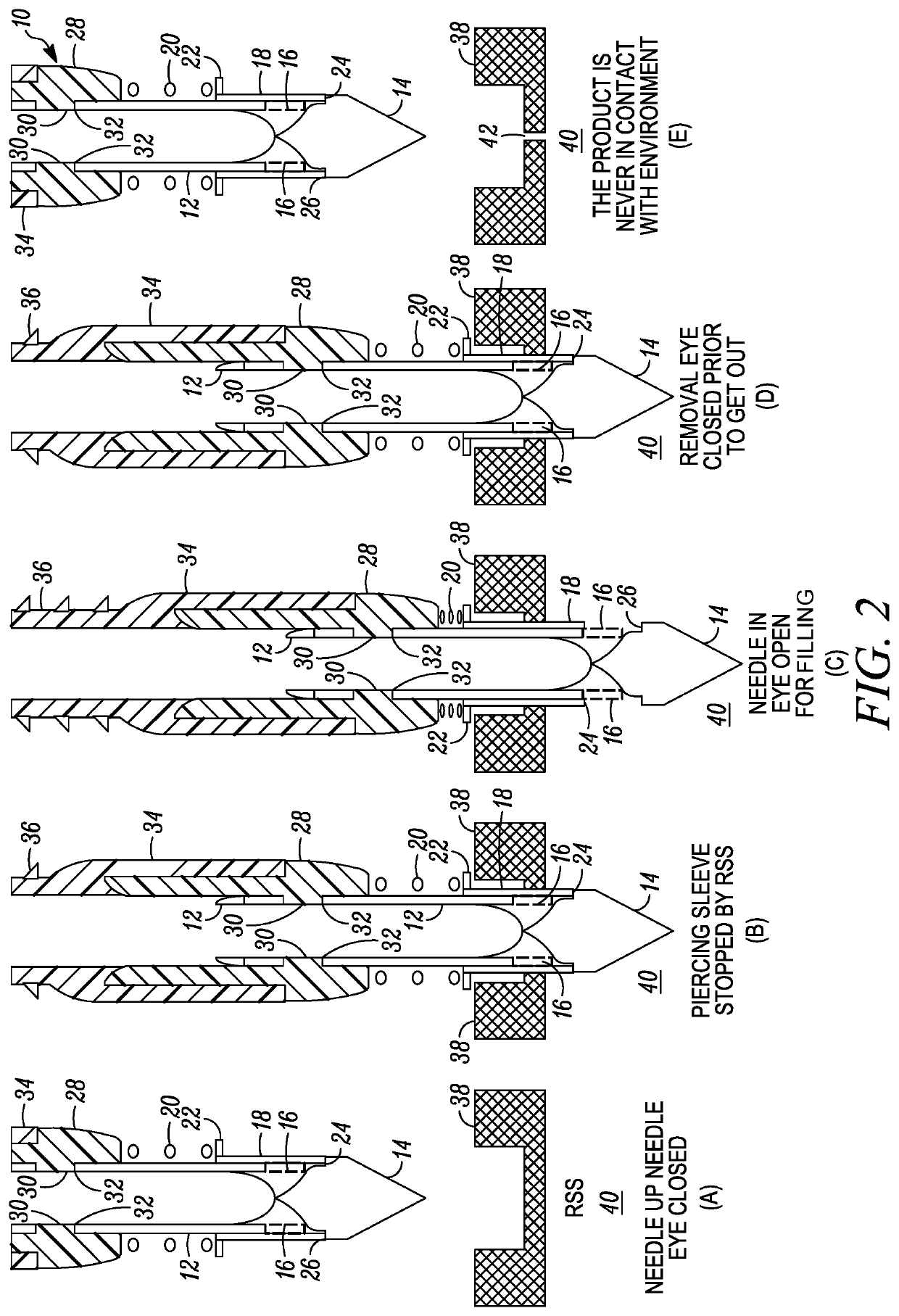
[0024]In FIGS. 1 and 2, a needle is indicated generally by the reference numeral 10. The needle 10 comprises a hollow shaft 12, a tip 14 formed at one end of the shaft; two ports 16, 16 in fluid communication with the interior of the hollow shaft 12, and a closure 18. In the illustrated embodiments, the two ports 16 are diametrically opposed relative to each other; however, as may be recognized by those of ordinary skill in the pertinent art based on the teachings herein, the needle may define any number of ports that may define any of numerous different configurations and locations. The closure 18 and / or the shaft 12 is movable between (i) a first position wherein the closure closes the ports 16, as shown typically in FIG. 1, and (ii) a second position opening the ports 16, as shown typically in FIG. 2C. In the illustrated embodiment, when in the closed position, the closure 18 forms a substantially fluid-tight seal between the ports 16 and ambient atmosphere. The closure 18 is bia...


PUM

PropertyMeasurementUnit
lengthaaaaaaaaaa
diameteraaaaaaaaaa
thicknessaaaaaaaaaa

Abstract

A needle has a hollow shaft, a tip formed at one end of the shaft, one or more ports in fluid communication with the interior of the hollow shaft, and a closure. The closure and / or the shaft is movable between (i) a first position wherein the closure closes the port(s), and (ii) a second position opening the port(s).

Description

CROSS-REFERENCE TO RELATED APPLICATIONS[0001]This patent application is a continuation of U.S. patent application Ser. No. 13 / 450,306, filed Apr. 18, 2012, claiming benefit under 35 U.S.C. § 119(e) to U.S. Provisional Patent Application Ser. No. 61 / 476,523, entitled “Filling Needle and Method,” filed Apr. 18, 2011, which are hereby expressly incorporated by reference in its entirety as part of the present disclosure.FIELD OF THE INVENTION[0002]The present invention relates to needles, and more particularly, relates to filling needles and methods of filling with needles.BACKGROUND INFORMATION[0003]A typical prior art filling needle includes a hollow stainless steel shaft, a non-coring, conically-pointed tip fixedly secured to the distal end of the shaft, and diametrically opposed fluid ports proximal to the tip and in fluid communication between the interior of the shaft and the ambient atmosphere. One drawback encountered with prior art filling needles is that the interior of the ne...

Claims


Application Information

Patent Timeline
Patent Type & Authority Applications(United States)
IPC IPC(8): B65B3/00B65B39/00B65B39/12
CPCB65B3/003B65B39/12B65B39/004A61M5/32
Inventor PY, DANIEL
Owner DR PY INST LLC
Learn More