
Automatic adsorbent filling device for air separation radial flow adsorber

An automatic filling and adsorbent technology, which is applied in the direction of separation methods, dispersed particle separation, chemical instruments and methods, etc., can solve the problems of internal grid deformation, low filling efficiency, and inability to completely ensure uniform filling of adsorbents, etc.

Inactive Publication Date: 2021-07-06
广钢气体(广州)有限公司
View PDF9 Cites 0 Cited by
  • Summary
  • Abstract
  • Description
  • Claims
  • Application Information

AI Technical Summary

Problems solved by technology

[0005] In order to overcome the above-mentioned existing automatic filling system for adsorber filling, it is necessary to divide the annular filling space of the adsorber into multiple areas, and fill them sequentially according to a certain filling sequence. Uneven filling of the adsorbent, even if the filling sequence is correct, it cannot completely guarantee the uniform filling of the adsorbent in the annular filling space, which will cause the inner grid to be squeezed and deformed by the adsorbent, and the filling efficiency is low. The invention provides an air separation radial flow adsorber adsorbent automatic filling device

Method used


Image

  • Automatic adsorbent filling device for air separation radial flow adsorber

Examples


Embodiment 1

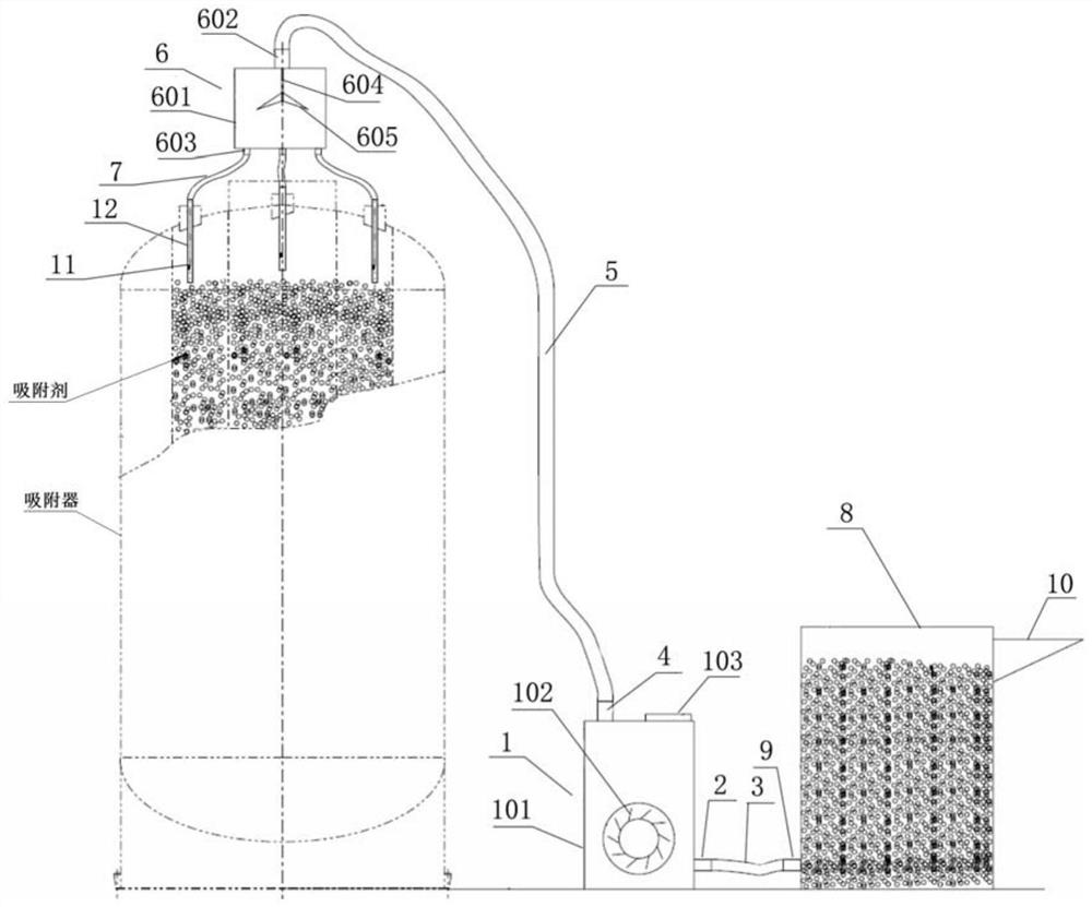
[0029] Such as figure 1 Shown, a kind of air separation radial flow adsorber adsorbent automatic filling device comprises a suction mechanism 1, an inlet pipe 3 connected to the material inlet 2 of the suction mechanism 1 at one end, and an inlet pipe 3 connected at one end to the suction mechanism 1. The outlet pipeline 5 on the material outlet 4 of the suction mechanism 1, which also includes a material equal distribution mechanism 6, the other end of the outlet pipeline 5 is connected with the inlet end of the material uniform distribution mechanism 6, and the material even distribution mechanism The outlet end of 6 is also provided with at least two material conveying pipes 7, one end of which is connected to the outlet end of the material equalizing mechanism 6, and the other end can be freely changed in position. In this way, the inlet pipe 3 on the suction mechanism 1 is connected to the adsorbent storage device, and then the outlet end of the material delivery pipe 7 i...

Embodiment 2

[0036] This embodiment is similar to Embodiment 1, the difference is that, as figure 1 As shown, this embodiment also includes an adsorbent silo 8, the other end of the inlet pipe 3 is connected to the adsorbent outlet 9 at the bottom of the adsorbent silo 8, and the top side of the adsorbent silo 8 is provided with Adsorbent inlet 10. When the adsorbent storage device is inconvenient to be directly connected to the inlet pipe 3 of the suction mechanism 1 , the adsorbent bin 8 can be used to transfer the adsorbent from the adsorbent storage device to the adsorbent bin 8 .

[0037] Such as figure 1 As shown, the end of the material conveying pipe 7 away from the material equalizing mechanism 6 is provided with a flow sensor 11 , and the flow sensor 11 is communicatively connected with the operating system panel 103 . The flow sensor 11 can monitor the flow rate of the adsorbent in each material conveying pipe 7, and transmit the monitoring data to the operating system panel 1...


PUM


Abstract

The invention provides an automatic adsorbent filling device for an air separation radial flow adsorber. The automatic adsorbent filling device for the air separation radial flow adsorber comprises a suction mechanism, an inlet pipeline with one end connected to a material inlet of the suction mechanism, an outlet pipeline with one end connected to a material outlet of the suction mechanism, and a material equipartition mechanism, wherein the other end of the outlet pipeline is connected with the inlet end of the material equipartition mechanism, the outlet end of the material equipartition mechanism is further provided with at least two material conveying pipes, one ends of the material conveying pipes are connected with the outlet end of the material equipartition mechanism, and the positions of the other ends of the material conveying pipes can be changed at will. According to the invention, adsorbent filling can be carried out in a plurality of areas of the annular filling space of the adsorber at the same time, so the adsorbent filling in the annular filling space is more uniform, and the inner grating of the annular filling space is effectively prevented from being extruded and deformed by the adsorbent.

Description

technical field [0001] The invention relates to the technical field of packing of adsorber packing, and more particularly, relates to an automatic packing device for adsorbent of an air separation radial flow adsorber. Background technique [0002] The adsorber is a very important piece of equipment in the air pre-treatment stage of the air separation system. Its operation is directly related to the safe operation of the entire air separation system. All air separation manufacturers at home and abroad attach great importance to this equipment and put it on the equipment. A lot of research has been done. [0003] After decades of development, the main forms of adsorbers are: vertical horizontal bed, horizontal horizontal bed, radial flow, etc. Among them, vertical horizontal bed and horizontal horizontal bed are the most commonly used in China. The adsorbent loading process of the horizontal horizontal bed is very simple. The user first stacks the adsorbent layer by layer on...

Claims


Application Information

Patent Timeline
Patent Type & Authority Applications(China)
IPC IPC(8): B01D53/04
CPCB01D53/04
Inventor 邓韬范胜标凌峰贲志山李伟楼旭铼周仁锋朱建豪鞠昊
Owner 广钢气体(广州)有限公司
Learn More