X-ray optical grating and method for the production thereof, and X-ray detector embodying same

a technology of optical grating and x-ray, which is applied in the direction of diaphragms for radiation diagnostics, instruments, tomography, etc., can solve the problems of x-ray measurement signal degradation, and achieve the effect of maintaining the quality of the measurement signal

Inactive Publication Date: 2012-04-24
PAUL SCHERRER INSTITUT +1
View PDF9 Cites 24 Cited by
  • Summary
  • Abstract
  • Description
  • Claims
  • Application Information

AI Technical Summary

Benefits of technology

[0008]An object of the present invention is to provide a method for the production of x-ray-optical gratings for x-ray dark field imaging and for x-ray phase contrast imaging, and such an x-ray-optical grating itself that enable a uniform filling of the grating gaps of a grating with regard to the level of the filling, such that ultimately the quality of the measurement signal is maintained.
[0009]The invention is based on the insight that it is possible to design the process of electroplating to fill the grating gaps with a material with high absorption coefficient so that the grating structures are deliberately over-plated, so all grating gaps across the entire grating surface are filled with a highly absorbent material to their complete height, and additionally a cohesive and uniform layer of this filling material is created (most importantly with a uniform height) over (atop) the grating webs. It is furthermore advantageous that an improved mechanical stability of the gratings is achieved as a beneficial side-effect, due to the additional cohesion of the grating gaps filled in the electroplating process.
[0013]An additional advantage of the layer is the increased mechanical strength the results therefrom. This is particularly advantageous if the gratings are used in a detector. In CT apparatuses of the 3rd generation with rotating detector, centrifugal forces between 20 and 40 g arise to which the gratings are exposed, and a strong mechanical stability is required.
[0014]The use of a plastic as a first material, advantageously polymethacrylate (PMMA) or an epoxy resin, has proven to be advantageous. These materials have a desired low x-ray absorption coefficient and are simple to handle in terms of their processing. Furthermore, epoxy resin in particular is very x-ray-insensitive.
[0018]It is advantageous to produce the x-ray-optical grating according to the method described above, namely to attach an x-ray-sensitive layer with an electrically conductive cover layer on a base plate, afterward to transfer a grating structure into the x-ray-sensitive layer via a lithographic method, wherein exposed and unexposed regions are created and the exposed regions of the x-ray-sensitive layer are dissolved so that a grating structure remains. A metal can subsequently be introduced into the grating interstices via electroplating so that a negative impression of a grating made of metal remains after removal of the x-ray-sensitive material and the base plate, and a grating made from a first material can be produced with this negative impression.

Problems solved by technology

These variances lead to a degradation of the measurement signal in x-ray dark field imaging and in x-ray phase contrast imaging, since the bands of generated high and low emission then deliver minima or maxima of different magnitudes that degrades the acquisition quality.

Method used


Image

  • X-ray optical grating and method for the production thereof, and X-ray detector embodying same
  • X-ray optical grating and method for the production thereof, and X-ray detector embodying same
  • X-ray optical grating and method for the production thereof, and X-ray detector embodying same

Examples


Embodiment Construction

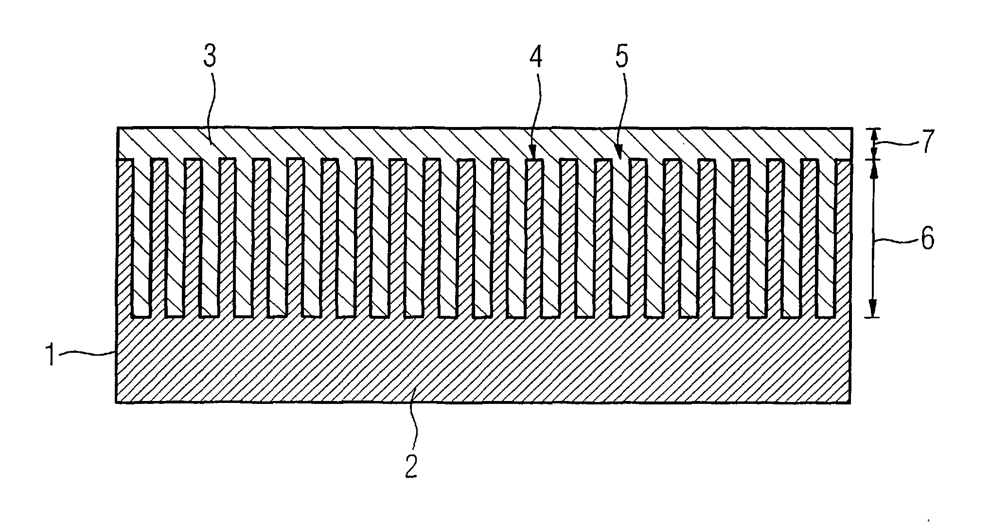
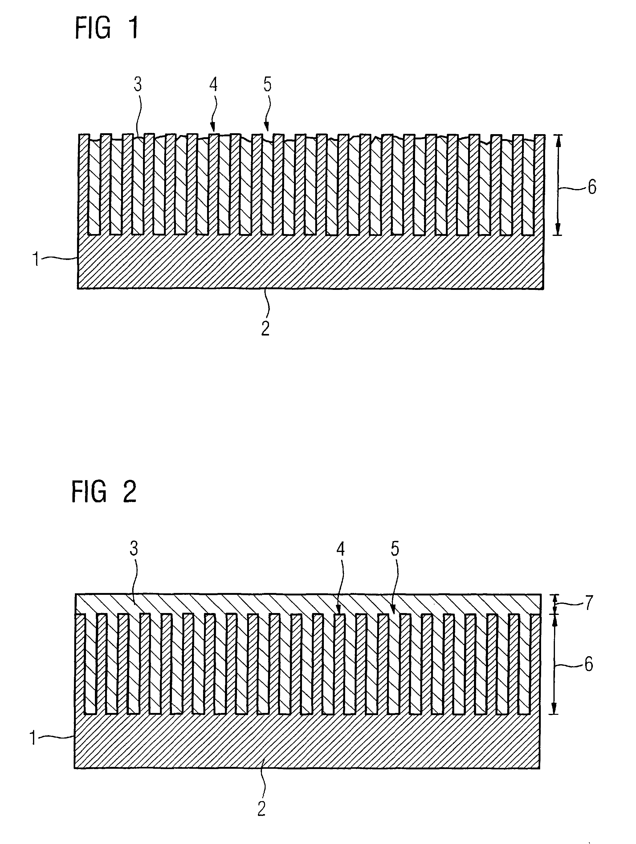
[0023]FIG. 1 shows a conventional x-ray-optical grating 1 that was produced according to the LIGA method. An x-ray-sensitive layer—this is for the most part a plastic such as polymethacrylate, abbreviated as PMMA—is applied on a base plate. A grating structure is subsequently transferred via lithographic exposure with, for example, parallel synchrotron radiation. Exposed and unexposed regions are hereby created, wherein the exposed regions are subsequently dissolved. In the next step, a metal is filled into the grating openings (spacings) by electroplating. In an electrolytic bath, a voltage is thereby applied between the grating and an anode made of the metal to be plated. By electrolysis, metal ions detach from the anode and deposit by reduction on the cathode, to produce the grating. This is continued until a complete negative impression of a grating has been created. With the use of this negative impression, the grating 1 with periodically arranged grating webs 4 and grating gap...


PUM

PropertyMeasurementUnit
thicknessaaaaaaaaaa
thicknessaaaaaaaaaa
aspect ratioaaaaaaaaaa

Abstract

In a method for the production of x-ray-optical gratings composed of a first material forming of periodically arranged grating webs and grating openings, a second material is applied by electroplating to fill the grid openings. The electroplating is continued until a cohesive layer of the second material with uniform height is created over the grating webs with this layer having a large absorption coefficient, the absorption properties of the grating structure of the grating are homogenized, so an improvement of the measurement signals that are generated with this grating is improved. Moreover, the mechanical stability of gratings produced in such a manner is improved.

Description

BACKGROUND OF THE INVENTION[0001]1. Field of the Invention[0002]The present invention concerns a method to produce x-ray-optical gratings, x-ray-optical gratings and an x-ray system for x-ray dark field imaging and for x-ray phase contrast imaging.[0003]2. Description of the Prior Art[0004]It is known to produce an x-ray optical grating as follows. An x-ray-sensitive layer with an electrically conductive cover layer is applied on a base plate and a grating structure is transferred by a lithographic method into the x-ray-sensitive layer, so exposed and unexposed regions are created. The exposed regions of the x-ray-sensitive layer is dissolved so that a grating structure remains; a metal is introduced into the grating interstices by electroplating. A negative imprint of a grating made of metal remains after removing the x-ray-sensitive material and the base plate. A grating made of a first material is produced with this negative imprint, wherein this grating having a number of period...

Claims


Application Information

Patent Timeline
Patent Type & Authority Patents(United States)
IPC IPC(8): G21K1/00
CPCG01T1/00G21K1/025G21K1/06A61B6/06G21K2207/005Y10T29/49A61B6/484A61B6/4092A61B6/4291A61B6/03
Inventor DAVID, CHRISTIANDONATH, TILMANHEMPEL, ECKHARDHOHEISEL, MARTINMATTHIS, BARBARAPFEIFFER, FRANZPOPESCU, STEFAN
Owner PAUL SCHERRER INSTITUT
Why Eureka
Try Eureka