Air conditioner for vehicle

a technology for air conditioners and vehicles, applied in vehicle components, vehicle heating/cooling devices, transportation and packaging, etc., can solve the problems of difficult control of air volume, large space occupation, and disadvantages of conventional air conditioners, so as to minimize thermal losses, reduce the width of air conditioners, and maximize the internal space of vehicles.

Inactive Publication Date: 2020-07-02
HANON SYST
View PDF0 Cites 1 Cited by
  • Summary
  • Abstract
  • Description
  • Claims
  • Application Information

AI Technical Summary

Benefits of technology

[0027]As described above, the air conditioner for a vehicle according to an embodiment of the present invention can directly control an amount of air passing through the evaporator and the heater core since the blower is arranged between the evaporator and the heater core.
[0028]Additionally, the evaporator and the heater core are individually arranged in different units to be erect and the blast fan of the blower is arranged to be erect. Therefore, the air conditioner for a vehicle according to the present invention can maximize the internal space of the vehicle since the width that the air conditioner occupies is reduced remarkably in comparison with the conventional air conditioner including the blast fan arranged to lie.
[0029]In addition, the air conditioner for a vehicle according to the present invention can minimize thermal losses since the evaporator and the heater core are individually arranged in different units, and can easily control the amount of air supplied to the heater core since the heater core directly communicates with the blast fan.

Problems solved by technology

However, the heater core 42 is relatively far away from the blast fan 35 since the air passes through the heater core 42 after passing through the evaporator 41, so it is not easy to control an air volume.
Now, development for reducing the size of the air conditioner is ongoing actively, but in the conventional arrangement of the semi-center type air conditioner 1 and parts, because the blast fan 35 lies in the whole length direction of the vehicle and the evaporator 41 and the heater core 42 are also arranged side by side in the whole length direction of the vehicle, the conventional air conditioner has a disadvantage in that it occupies a wide space.

Method used


Image

  • Air conditioner for vehicle
  • Air conditioner for vehicle
  • Air conditioner for vehicle

Examples


Embodiment Construction

[0034]In order to fully understand the present invention, exemplary embodiments of the invention will be described with reference to the accompanying drawings. The embodiments of the present invention may be modified in many different forms and the scope of the invention should not be limited to the embodiments set forth herein. Rather, these embodiments are provided so that this disclosure will be thorough and complete, and will fully convey the concept of the invention to those skilled in the art. In the drawings, the shapes and dimensions may be exaggerated for clarity, and the same reference numerals will be used throughout to designate the same or like components. A detailed explanation of known related functions and constitutions may be omitted to avoid unnecessarily obscuring the subject matter of the present invention.

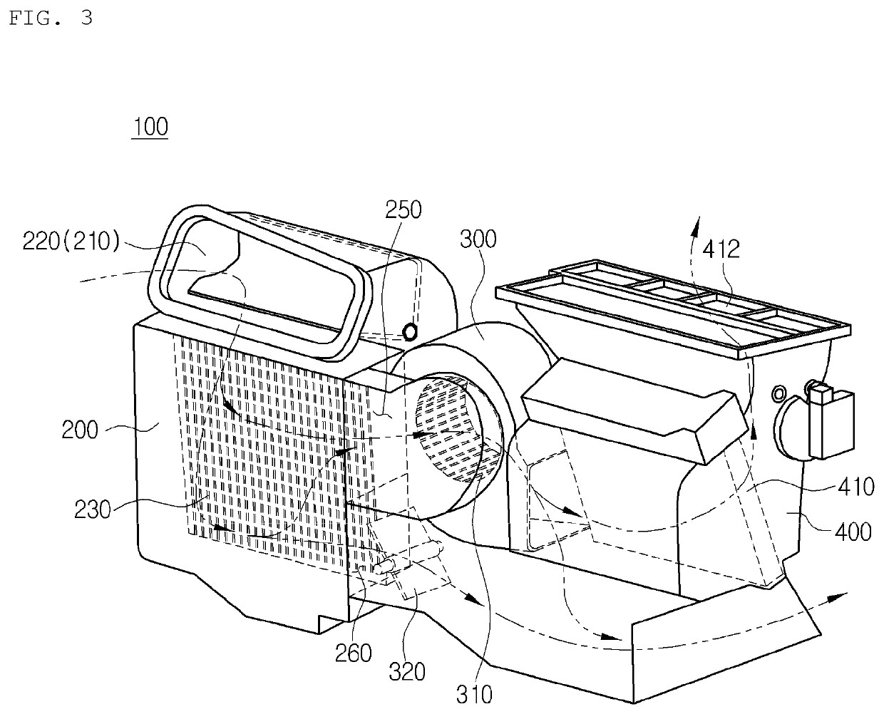
[0035]FIGS. 3 to 6 are perspective views showing an air conditioner for a vehicle according to the present invention.

[0036]As shown in FIGS. 3 to 6, the air co...


PUM


Abstract

Disclosed is an air conditioner for a vehicle. The air conditioner includes a blower unit having an air blower which is erect, wherein the blower unit is arranged between an evaporator unit having an evaporator and a heater unit having a heater core in order to remarkably reduce the width of the air conditioner and maximize an internal space of the vehicle.

Description

TECHNICAL FIELD[0001]The present invention relates to an air conditioner for a vehicle, and more particularly, to an air conditioner for a vehicle, which includes a blower arranged between an evaporator and a heater core in order to maximize an internal space of the vehicle.BACKGROUND ART[0002]In general, an air conditioner for a vehicle is an apparatus for cooling or heating the interior of the vehicle by cooling or heating through the process of introducing outdoor air into the interior of the vehicle or circulating indoor air of the vehicle. Such an air conditioner for a vehicle includes an evaporator for cooling the inside of an air-conditioning case; a heater core for heating the inside of the air-conditioning case; and a mode converting door for selectively blowing the air cooled by the evaporator or heated by the heater core toward parts of the interior of the vehicle.[0003]According to mounted structures of an air blower unit, an evaporator unit and a heater core unit, such ...

Claims


Application Information

Patent Timeline
Patent Type & Authority Applications(United States)
IPC IPC(8): B60H1/00B60H1/32
CPCB60H1/00207B60H1/3233B60H1/00671B60H1/00564B60H1/00028B60H1/00885B60H2001/00242B60H2001/002B60H1/00064B60H2001/00107B60H1/00521B60H1/00664
Inventor HAN, SEONG SEOKKANG, SUNG HOLEE, JEONG JAEUM, BOO YONGCHO, JUNG WON
Owner HANON SYST
Why Eureka
Try Eureka