Variable displacement vane pump and method of manufacturing the same

a vane pump and variable displacement technology, applied in the direction of positive displacement liquid engines, piston pumps, liquid fuel engines, etc., can solve the problems of unbalanced wear and seizing, each vane contact or interfere at its corner, etc., to reduce weight and size, maximize internal space, and minimize size

Inactive Publication Date: 2008-05-22
HITACHI ASTEMO LTD
View PDF3 Cites 2 Cited by
  • Summary
  • Abstract
  • Description
  • Claims
  • Application Information

AI Technical Summary

Benefits of technology

[0003]When a variable displacement vane pump is employed in an automotive vehicle, it is desired to reduce the weight and size of the variable displacement vane pump while increasing the output of the variable displacement vane pump. In order to provide a maximized internal space with a minimized size, the pump body is made of a light material such as an aluminum alloy, and the thickness of the walls of the pump body is minimized, for example. In such a case, there is a possibility that when the internal pressure of the pump chambers are high in the second region of the space defined between the rotor and the cam ring in which the discharge port is formed, the cylinder portion of the front body is deformed radially outside so that the inner radial surface of the cylinder portion is inclined. The inclination of the inner radial surface of the cylinder portion of the front body, which is significant especially in a portion of the cylinder portion radially outside of the second region, results in inclination of the longitudinal axes of the adapter ring and the cam ring. The inclination of the inner radial peripheral surface of the cam ring causes inclination of the vanes, because the outer edge of each vane remains in edge-to-surface contact with the inner peripheral surface of the cam ring. On the other hand, the rotor is in position with no inclination, because the rotor is fixed to the drive shaft. Accordingly, each vane extends longitudinally of the drive shaft outside the rotor. As a result, there is a possibility that each vane contacts or interferes at its corner with the longitudinal end surface of the rear body and the longitudinal end surface of the pressure plate. This may cause unbalanced wear and seizing due to friction on the longitudinal end surface of the rear body and the longitudinal end surface of the pressure plate.

Problems solved by technology

As a result, there is a possibility that each vane contacts or interferes at its corner with the longitudinal end surface of the rear body and the longitudinal end surface of the pressure plate.
This may cause unbalanced wear and seizing due to friction on the longitudinal end surface of the rear body and the longitudinal end surface of the pressure plate.

Method used


Image

  • Variable displacement vane pump and method of manufacturing the same
  • Variable displacement vane pump and method of manufacturing the same
  • Variable displacement vane pump and method of manufacturing the same

Examples


first embodiment

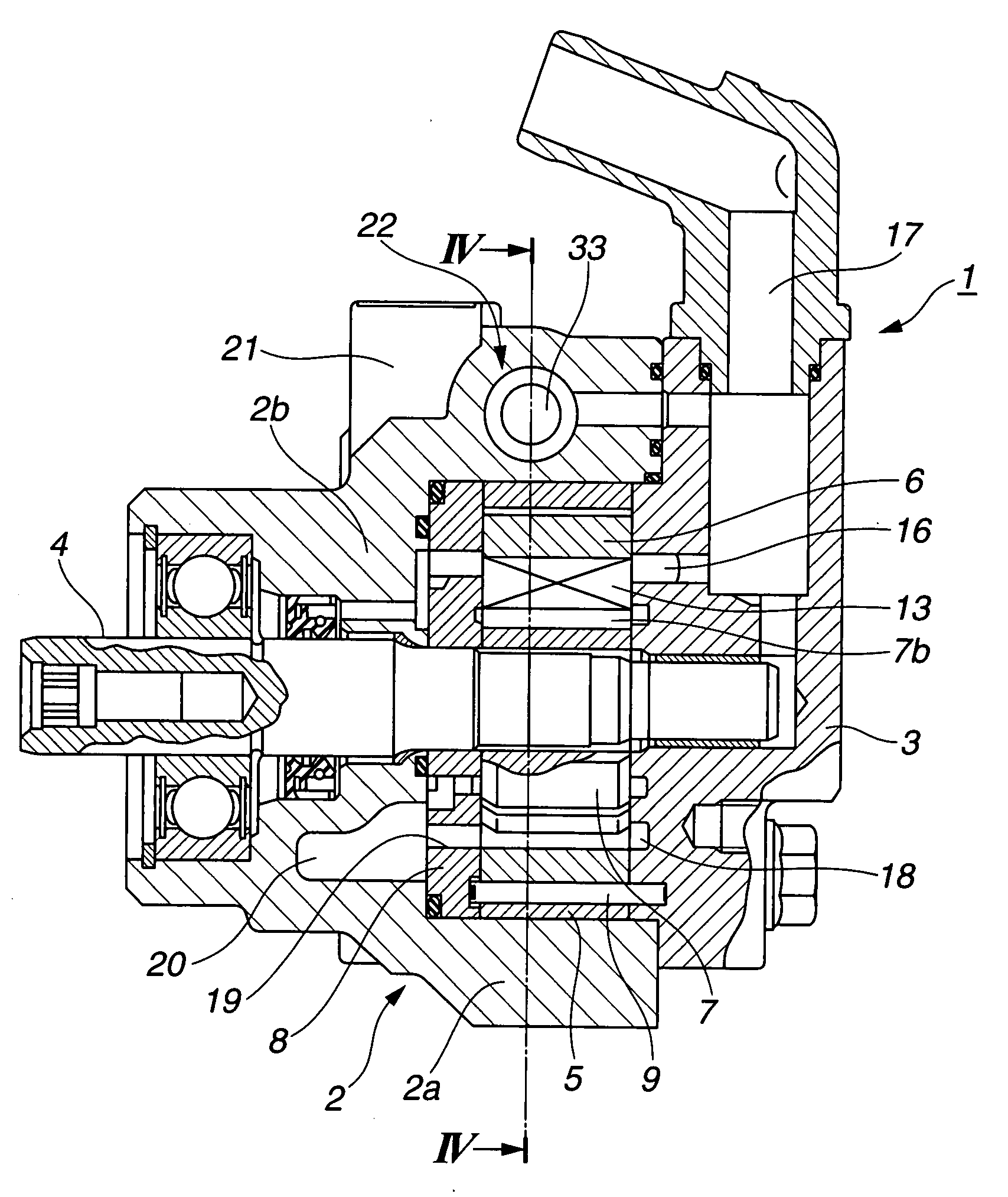
[0023]The following describes a variable displacement vane pump according to the present invention with reference to FIGS. 1 to 4. This variable displacement vane pump may be employed in an automotive power steering system. For ease of understanding, various directional terms, such as, right, left, upper, lower, rightward and the like are used in the following description. Such terms are to be understood with respect to a drawing or drawings on which corresponding part or portion is shown. As shown in FIGS. 3 and 4, a variable displacement vane pump 1 generally includes a front body 2 as a first body, a rear body 3 as a second body, a drive shaft 4, an adapter ring 5, a cam ring 6, a rotor 7, and a pressure plate 8. Front body 2 is made of a light material such as an aluminum alloy. Front body 2 includes a cylinder portion 2a having an inner space extending longitudinally therethrough, and a base portion 2b covering a first longitudinal end of the inner space of cylinder portion 2a....

second embodiment

[0048] adapter ring 5 can be easily formed by sintering, because the provision of inner and outer inclined surfaces 35a and 35b is effective for making it easy to draw the adapter ring 5 from the sintering mold.

[0049]One of the angle of inclination θ2 and angle of inclination θ3 may be set to be equal to zero. This means that inner inclined surface 35a is provided and no outer inclined surface 35b is provided, or that no inner inclined surface 35a is provided and outer inclined surface 35b is provided. In such a case, the other of the angle of inclination θ2 and angle of inclination θ3 is set to be equal to about 0.08°, similarly as angle of inclination θ1 of inclined surface 34 according to the first embodiment.

[0050]The following describes a variable displacement vane pump according to a third embodiment of the present invention with reference to FIG. 6. The third embodiment is constructed based on the first embodiment, and different from the first embodiment in that radial thickn...

third embodiment

[0053] the three-dimensional shape of pivoting contact area 11 of adapter ring 5 is effective for preventing unbalanced wear and seizing of rear body 3 and pressure plate 8, wherever cam ring 6 is positioned or however the pump discharge pressure is set.

[0054]In case the variable displacement vane pump according to the third embodiment is exemplified in an automotive power steering system, the variable displacement vane pump is effective, when the steering wheel is turned while the vehicle is at rest or running at low speed, that is, when the displacement of cam ring 6 is relatively large so that the pump discharge pressure is high, and is effective also when the vehicle is running at middle or high speed, that is, when the displacement of cam ring 6 is relatively small so that the pump discharge pressure is low.

[0055]The following describes a variable displacement vane pump according to a fourth embodiment of the present invention with reference to FIGS. 7 and 8. The fourth embodim...


PUM

PropertyMeasurementUnit
angle of inclination θ1aaaaaaaaaa
angle of taper θ4aaaaaaaaaa
angle of inclinationaaaaaaaaaa

Abstract

A variable displacement vane pump includes a first body, a second body, an adapter ring, a cam ring, and a rotor. The first body includes a cylinder portion, and a base portion covering a first longitudinal end of an inner space of the cylinder portion. The second body covers a second longitudinal end of the inner space of the first body. The adapter ring has an outer radial periphery fitted and fixed to an inner radial periphery of the cylinder portion of the first body. The cam ring is mounted inside the adapter ring and supported by the adapter ring for lateral motion in contact with the contact area of the adapter ring. The rotor is mounted inside the cam ring. The adapter ring has a radial thickness that gradually increases when followed longitudinally of the adapter ring from the base portion of the first body toward the second body.

Description

BACKGROUND OF THE INVENTION[0001]The present invention relates generally to variable displacement pumps, and more particularly to variable displacement vane pumps useful for automotive continuously variable transmissions and automotive power steering systems.[0002]Japanese Patent Application Publication No. 7-119648 discloses a variable displacement vane pump for an automotive power steering system. This variable displacement vane pump generally includes a pump body, an adapter ring, a cam ring, a rotor, and a pressure plate. The pump body includes a front body and a rear body which are coupled to form a chamber therebetween. Specifically, the front body includes a cylinder portion having an inner space extending longitudinally therethrough, and a base portion covering a first longitudinal end of the inner space of the cylinder portion, while the rear body covers a second longitudinal end of the inner space of the front body. The adapter ring is mounted in the inner space of the pum...

Claims


Application Information

Patent Timeline
Patent Type & Authority Applications(United States)
IPC IPC(8): F04B7/04B23P15/00
CPCF01C21/108F04C2/3442Y10T29/49245Y10T29/49236F04C14/226
Inventor YAMAMURO, SHIGEAKINOGAMI, TADAHIKO
Owner HITACHI ASTEMO LTD
Why Eureka
Try Eureka