
Inductor component

Inactive Publication Date: 2020-07-02
PANASONIC INTELLECTUAL PROPERTY MANAGEMENT CO LTD
View PDF0 Cites 0 Cited by
  • Summary
  • Abstract
  • Description
  • Claims
  • Application Information

AI Technical Summary

Benefits of technology

The patent is claiming that subjecting an inductor component to reflow-soldering improves its ability to stick to solder.

Problems solved by technology

To cope with such high-current applications, the devices have large sizes, and arise problems of vibration resistance in particular in automotive applications accordingly.

Method used


Image

  • Inductor component
  • Inductor component
  • Inductor component

Examples


Embodiment Construction

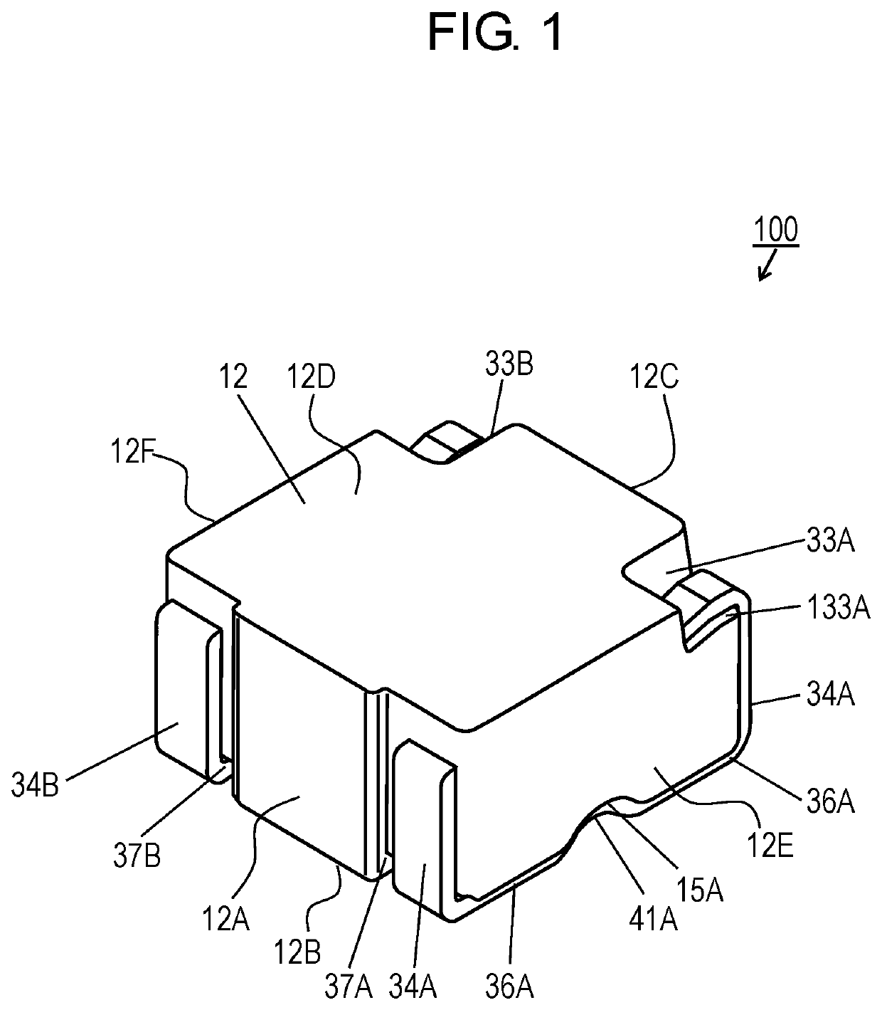
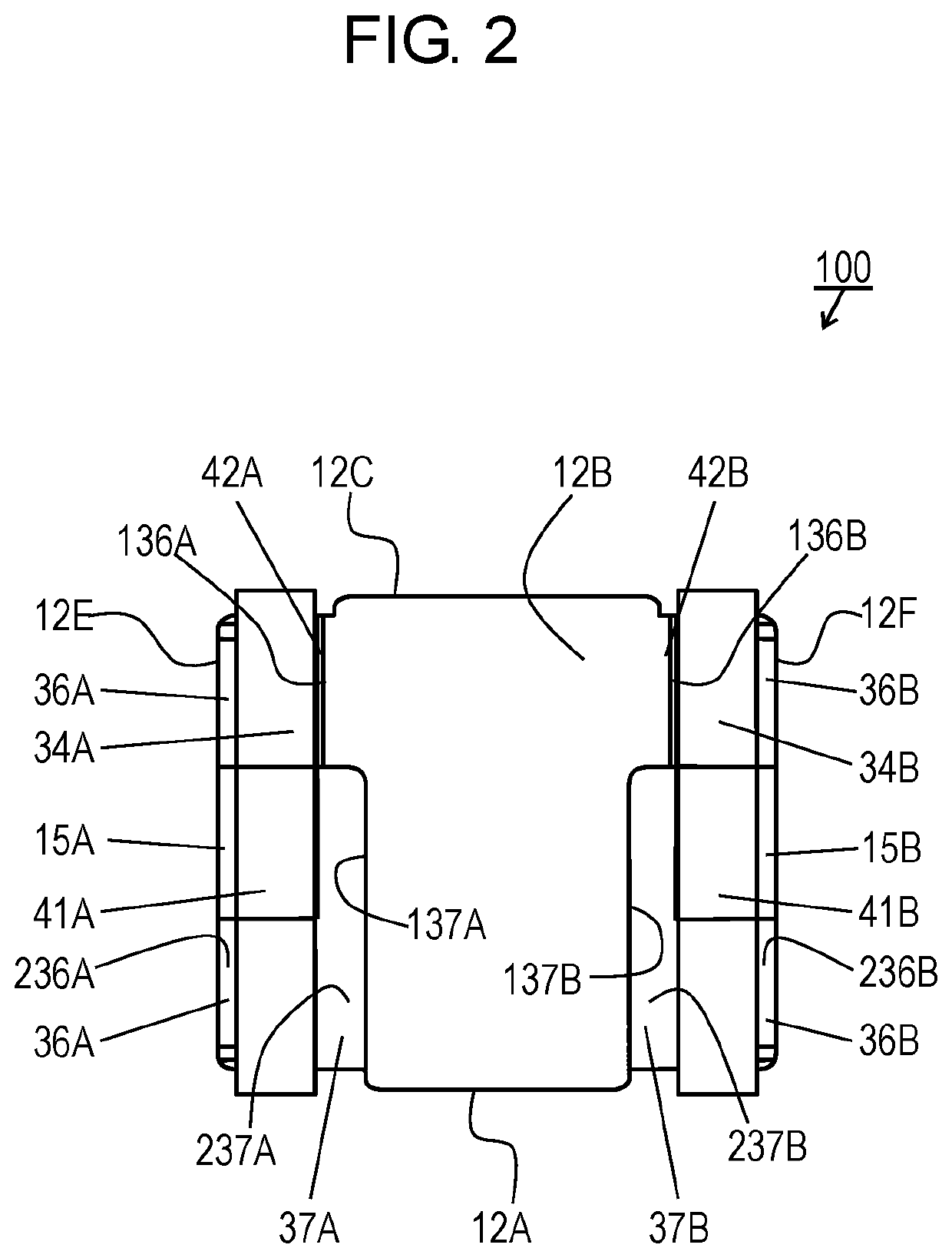
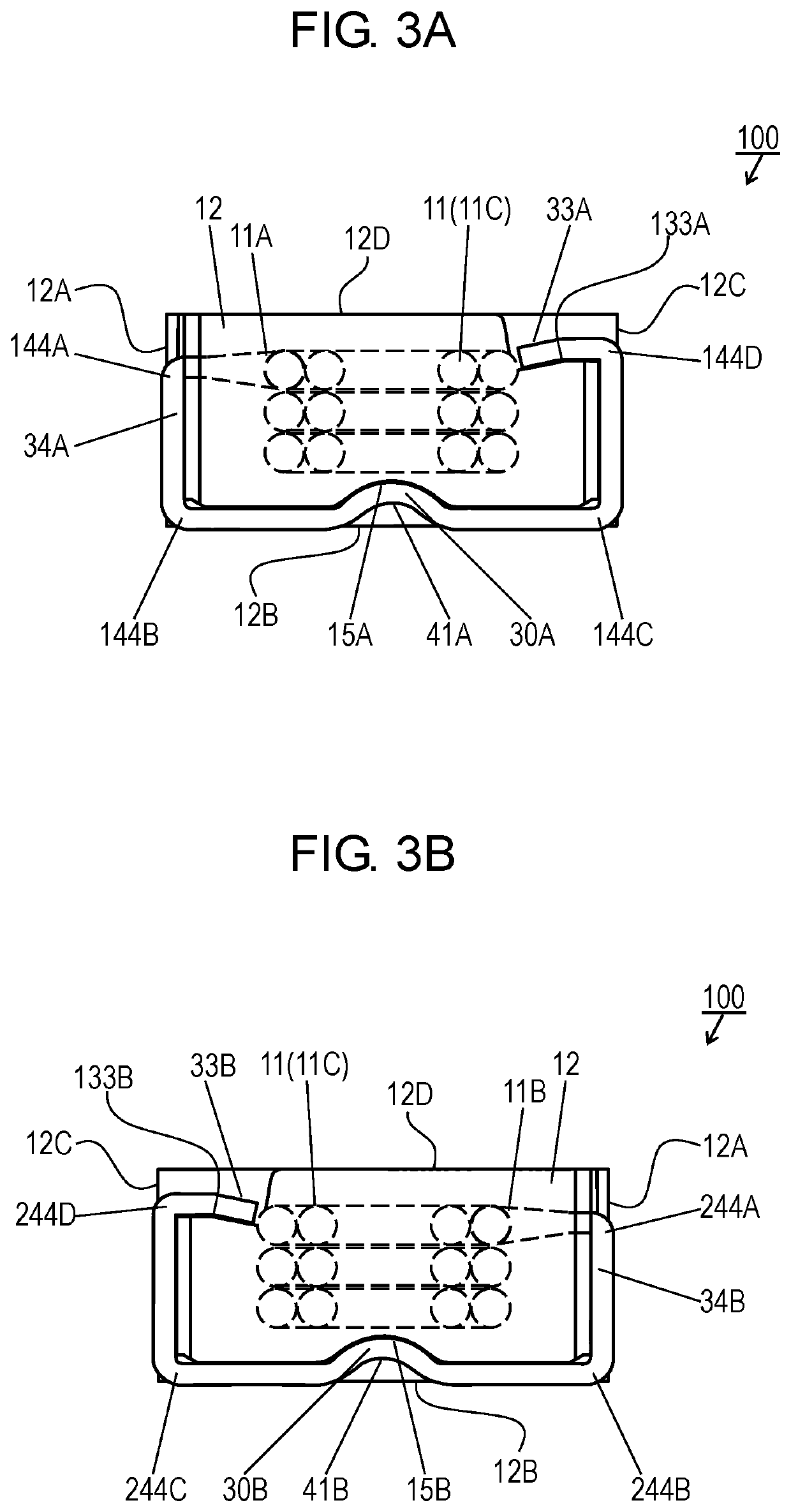
[0021]FIG. 1 is a top perspective view of inductor component 100 according to an exemplary embodiment. FIG. 2 is a bottom plan view of inductor component 100. FIGS. 3A and 3B are side views of inductor component 100. FIG. 4 is a bottom perspective view of inductor component 100.

[0022]Inductor component 100 includes coil 11, package 12, and external electrodes 34A and 34B. FIG. 5 is a bottom perspective view of package 12.

[0023]Package 12 is made of magnetic material. Coil 11 is embedded in package 12. In FIGS. 3A and 3B, coil 11 embedded in the package is indicated by dashed lines. Coil 11 is made of wound conductive wire 11C having ends 11A and 11B.

[0024]Package 12 includes: bottom surface 12B, top surface 12D opposite to bottom surface 12B, side surface 12A, side surface 12C opposite to side surface 12A, side surface 12E connected to side surface 12A and side surface 12C, and side surface 12F opposite to side surface 12E. Side surface 12A is connected to top surface 12D and bottom...


PUM


Abstract

An inductor component includes a package, a coil embedded in the package, a first external electrode extending from a first end of the coil, and a second external electrode extending from a second end of the coil. The package has a bottom surface, a top surface, first and second side surfaces opposite to each other, and third and fourth side surfaces opposite to each other. The bottom surface of the package has a first step recess therein sinking toward the top surface, opening to the third side surface, and contacting the first external electrode. The bottom surface of the package further has a second step recess therein sinking toward the top surface, opening to the fourth side surface, and contacting the second external electrode. The bottom surface has a third step recess therein connected to the first step recess and sinking toward the top surface. The bottom surface has a fourth step recess therein connected to the second step recess and sinking toward the top surface. Upon being subjected to reflow-soldering, the inductor component enhances wettability to solder.

Description

TECHNICAL FIELD[0001]The present invention relates to an inductor component for use in various electronics devices.BACKGROUND ART[0002]Inductor components used in devices, such as DC-DC converters, around engines of vehicles have been used in high electric-current applications. To cope with such high-current applications, the devices have large sizes, and arise problems of vibration resistance in particular in automotive applications accordingly.[0003]For inductor components for use in such high electric-current applications, the applicant of the application previously proposed an inductor component featuring improved vibration resistance (see PTL 1).[0004]The inductor component disclosed in PTL 1 includes a package made of magnetic material in which a coil electrode is embedded. The coil electrode is made of a wound conductive wire. both ends of the coil electrode is led out from a side surface of the package, bent at its lead-out position toward the bottom surface of the package, ...

Claims


Application Information

Patent Timeline
IPC IPC(8): H01F27/29H01F27/28H01F27/32
CPCH01F27/327H01F27/292H01F27/2823H01F17/04H01F2017/048H01F27/2828
Inventor KATAOKA, KEITOUEDA, HIDEKI
Owner PANASONIC INTELLECTUAL PROPERTY MANAGEMENT CO LTD
Learn More