
Piezoelectric device and cover sealing method and apparatus therefor, cellular phone apparatus using piezoelectric device and electronic apparatus using piezoelectric device

Active Publication Date: 2006-06-13
SEIKO EPSON CORP
View PDF16 Cites 6 Cited by
  • Summary
  • Abstract
  • Description
  • Claims
  • Application Information

AI Technical Summary

Benefits of technology

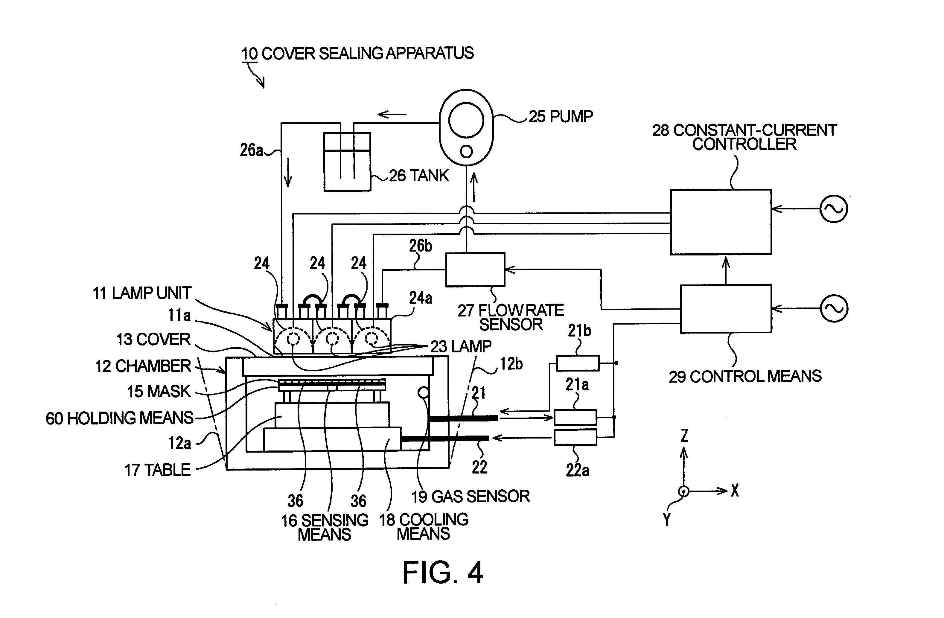
[0028]In the construction of the first aspect of the present invention, the light beams from the halogen lamps are used to permit light beam irradiation within a predetermined range. Therefore, an effective heating range can be extended, and thus a plurality of packages can be sealed with the covers by simultaneously heating the bottoms of the packages, as compared with a focused narrow light beam such as a laser beam. Furthermore, the time required to heat to a temperature necessary for sealing is short to shorten a total heating time, as compared with the use of a belt furnace having a heating means comprising a heating wire. Therefore, the structure in each of the packages is less adversely affected by heat.
[0084]In the construction of the twenty-seventh aspect of the present invention, the metal coating having high wettability with the sealing material is provided on the inner surfaces of the stepped portion and the first through hole, and thus the melted sealing material easily adheres to the inner surfaces of the stepped portion and the first through hole, thereby forming a structure capable of reducing or preventing the sealing material from further entering in the package.

Problems solved by technology

Particularly, the sealing apparatus 1 including the belt furnace requires a long standing time, and thus much time is required to start the sealing apparatus 1 when the temperature decreases at a break of production.
Furthermore, the heaters 3 must be heated to about 600° C. to heat the brazing material 8 to 360° C. Therefore, the sealing method is very wasteful.

Method used


Image

  • Piezoelectric device and cover sealing method and apparatus therefor, cellular phone apparatus using piezoelectric device and electronic apparatus using piezoelectric device
  • Piezoelectric device and cover sealing method and apparatus therefor, cellular phone apparatus using piezoelectric device and electronic apparatus using piezoelectric device
  • Piezoelectric device and cover sealing method and apparatus therefor, cellular phone apparatus using piezoelectric device and electronic apparatus using piezoelectric device

Examples


Embodiment Construction

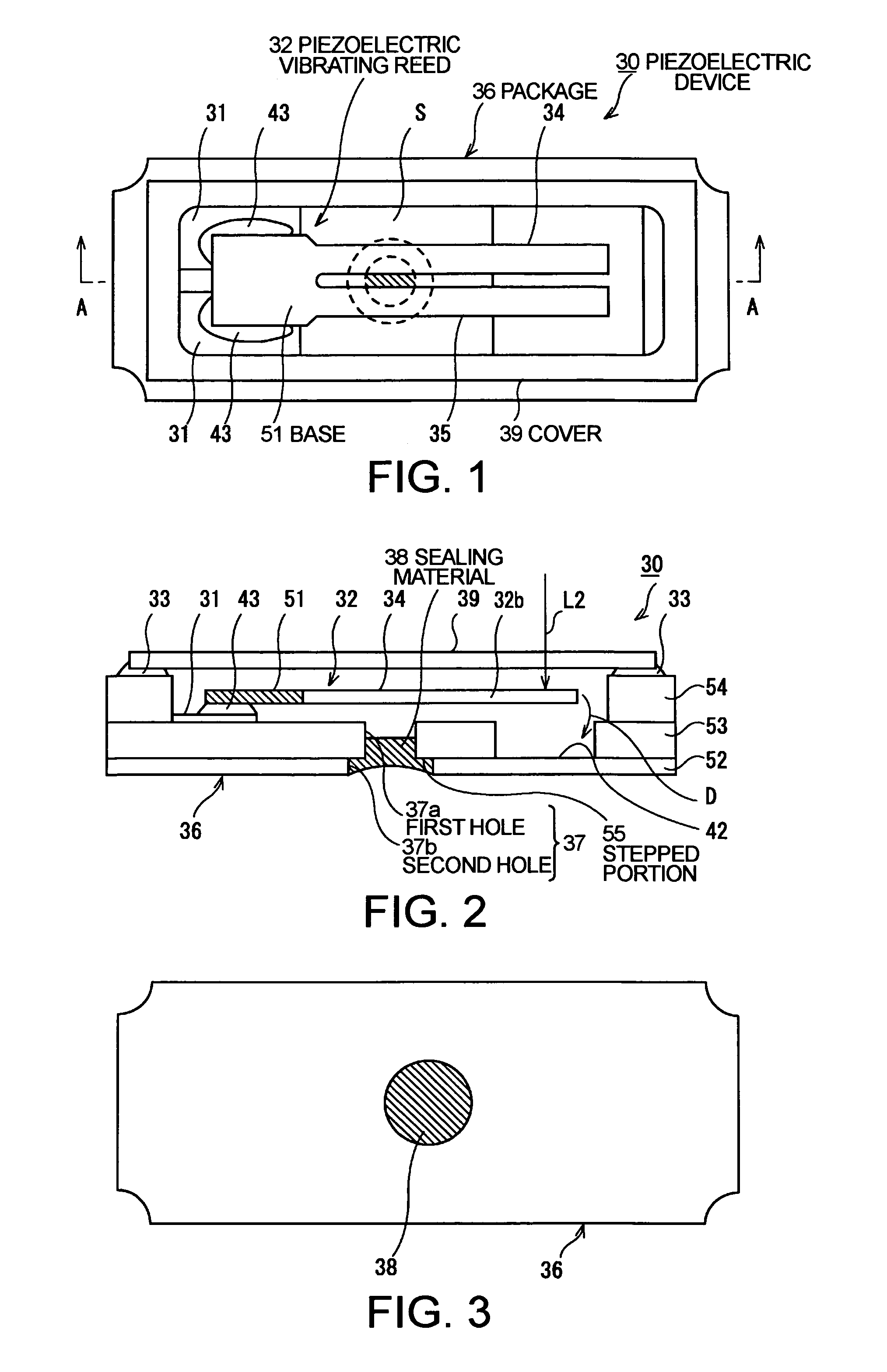
[0119]FIG. 1 shows a piezoelectric device according to a first exemplary embodiment of the present invention. FIG. 1 is a schematic plan view of the piezoelectric device, FIG. 2 is a schematic sectional view of the piezoelectric device taken along plane A—A in FIG. 1, and FIG. 3 is a bottom plan view of the piezoelectric device shown in FIG. 1.

[0120]In these drawings, a piezoelectric device 30 constitutes a piezoelectric vibrator as an example, and the piezoelectric device 30 includes a piezoelectric vibrating reed 32 contained in a package 36. The package 36 includes substrates composed of an aluminum oxide sintered material obtained by, for example, sintering a laminate of ceramic green sheets. Each of the substrates has a predetermined hole formed therein so that a predetermined internal space S is formed when the substrates are laminated.

[0121]Namely, as shown in FIG. 2, the package 36 of this exemplary embodiment includes, for example, a first laminated substrate 52, a second l...


PUM


Abstract

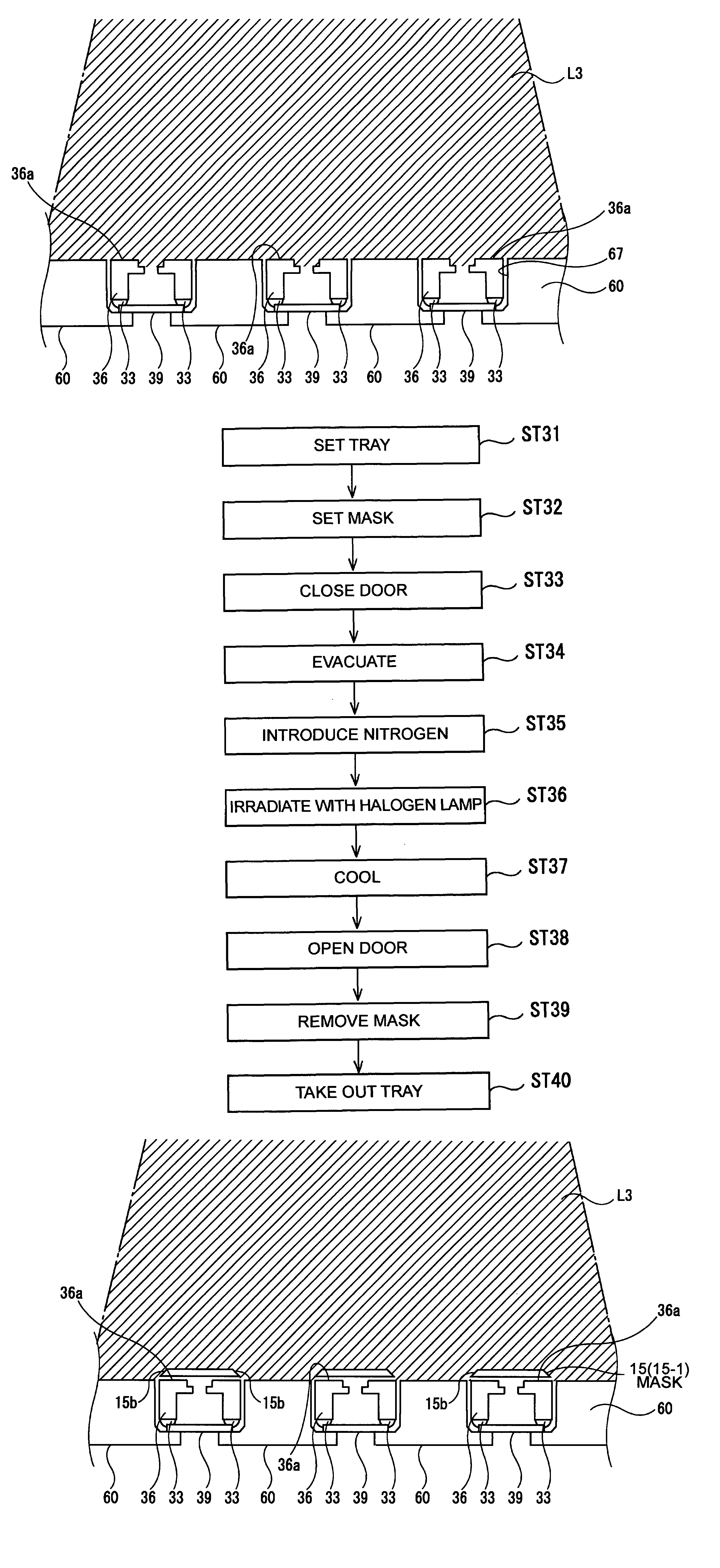
The invention provides a method of sealing piezoelectric devices with covers capable of rapidly and securely sealing a plurality of packages or many packages of piezoelectric devices with covers. A piezoelectric device includes a package in which a piezoelectric vibrating reed is partially supported and fixed, and a cover fixed to the packages. In a method of sealing the packages with the covers, a plurality of the packages are arranged with the bottoms facing halogen lamps, so that the bottoms are irradiated with the light beams from the halogen lamps to thermally melt a brazing material disposed between the packages and the covers.

Description

BACKGROUND OF THE INVENTION[0001]1. Field of Invention[0002]The present invention relates to a piezoelectric device including a piezoelectric vibrating reed contained in a package, and to an enhancement in a method of sealing the packages.[0003]2. Description of Related Art[0004]Small information apparatuses, such as HDDs (hard disk drives), mobile computers, and IC cards, and electronic apparatuses, such as cellular phones and the like, use a piezoelectric device, such as a piezoelectric vibrator, a piezoelectric oscillator, or the like, which includes a piezoelectric vibrating reed contained and sealed in a package.[0005]Such a piezoelectric device is formed by setting a piezoelectric vibrating reed in a ceramic package having the open top, and fixing a cover to the package to seal the package.[0006]The piezoelectric device is manufactured as schematically shown in a flow chart of FIG. 28.[0007]First, a box-like package including a piezoelectric material, such as ceramic or the li...

Claims


Application Information

Patent Timeline
IPC IPC(8): H01L21/00H01L21/48H01L23/02H01L41/053H01L41/09H01L41/18H01L41/22H01L41/23H01L41/313H02N2/00H03H3/02H03H9/02H03H9/10H03H9/21
CPCH01L41/053H03H3/02H03H9/21H03H9/1021H03H2003/026
Inventor KAWAUCHI, OSAMUSAKURAI, KENJIMURATA, KENICHIRO
Owner SEIKO EPSON CORP
Learn More