
Electroluminescent Display Apparatus

a technology of display apparatus and electroluminescent light, which is applied in the direction of electrical apparatus, semiconductor devices, instruments, etc., can solve the problems of reducing the yield of process, degrading the reliability of the display apparatus, and abnormal color tone at a side viewing angl

Active Publication Date: 2020-07-02
LG DISPLAY CO LTD
View PDF0 Cites 13 Cited by
  • Summary
  • Abstract
  • Description
  • Claims
  • Application Information

AI Technical Summary

Benefits of technology

This patent is about improving the quality of an electroluminescent display by attaching a polarizer or placing the back plate in the right position. The inventors discovered that by using an alignment reference unit in the non-display area, the polarizer or back plate could be accurately aligned with the display panel. This alignment reference unit also serves as a guide to attach the polarizer without misaligning it. Overall, this patent aims to enhance the accuracy and precision of the display.

Problems solved by technology

However, when the polarizer is not attached to the display panel at an accurate position, the color tone becomes abnormal at a side viewing angle.
Further, when a back plate is disposed on a rear surface of a substrate to support the substrate, there is a problem in that a process yield is lowered due to misalignment of the back plate and the substrate.
However, when the alignment reference unit is formed in a specific area, a step is caused between an area where the alignment reference unit is formed and an area where the alignment reference unit is not formed, which may adversely affect the processes after the process of forming the alignment reference unit so that the reliability of the display apparatus is degraded.

Method used


Image

  • Electroluminescent Display Apparatus
  • Electroluminescent Display Apparatus
  • Electroluminescent Display Apparatus

Examples


Embodiment Construction

[0029]Advantages and characteristics of the present disclosure and a method of achieving the advantages and characteristics will be clear by referring to exemplary embodiments described below in detail together with the accompanying drawings. However, the present disclosure is not limited to the exemplary embodiments disclosed herein but will be implemented in various forms. The exemplary embodiments are provided by way of example only so that those skilled in the art can fully understand the disclosures of the present disclosure and the scope of the present disclosure. Therefore, the present disclosure will be defined only by the scope of the appended claims.

[0030]The shapes, sizes, ratios, angles, numbers, and the like illustrated in the accompanying drawings for describing the exemplary embodiments of the present disclosure are merely examples, and the present disclosure is not limited thereto. Like reference numerals generally denote like elements throughout the specification. F...


PUM


Abstract

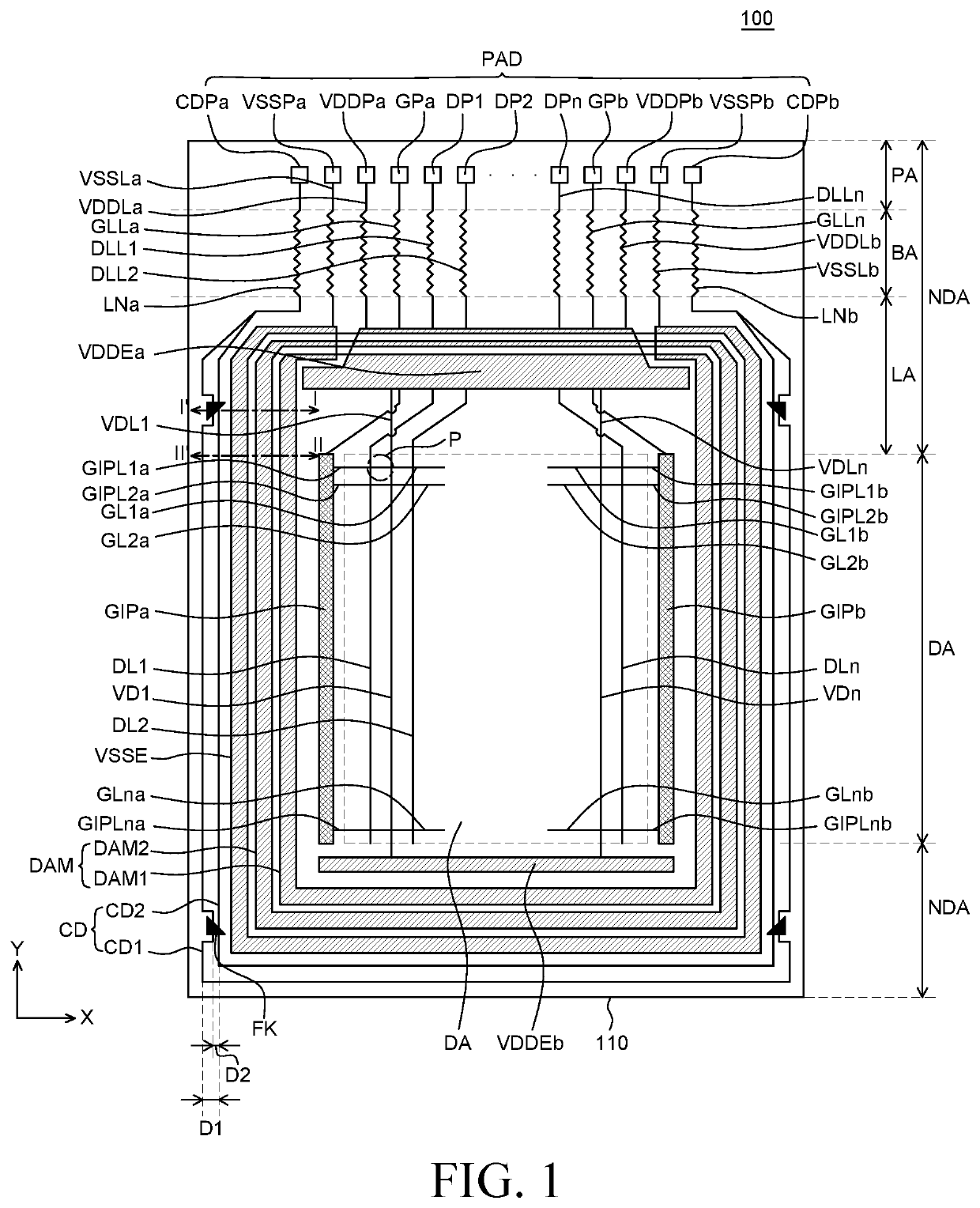
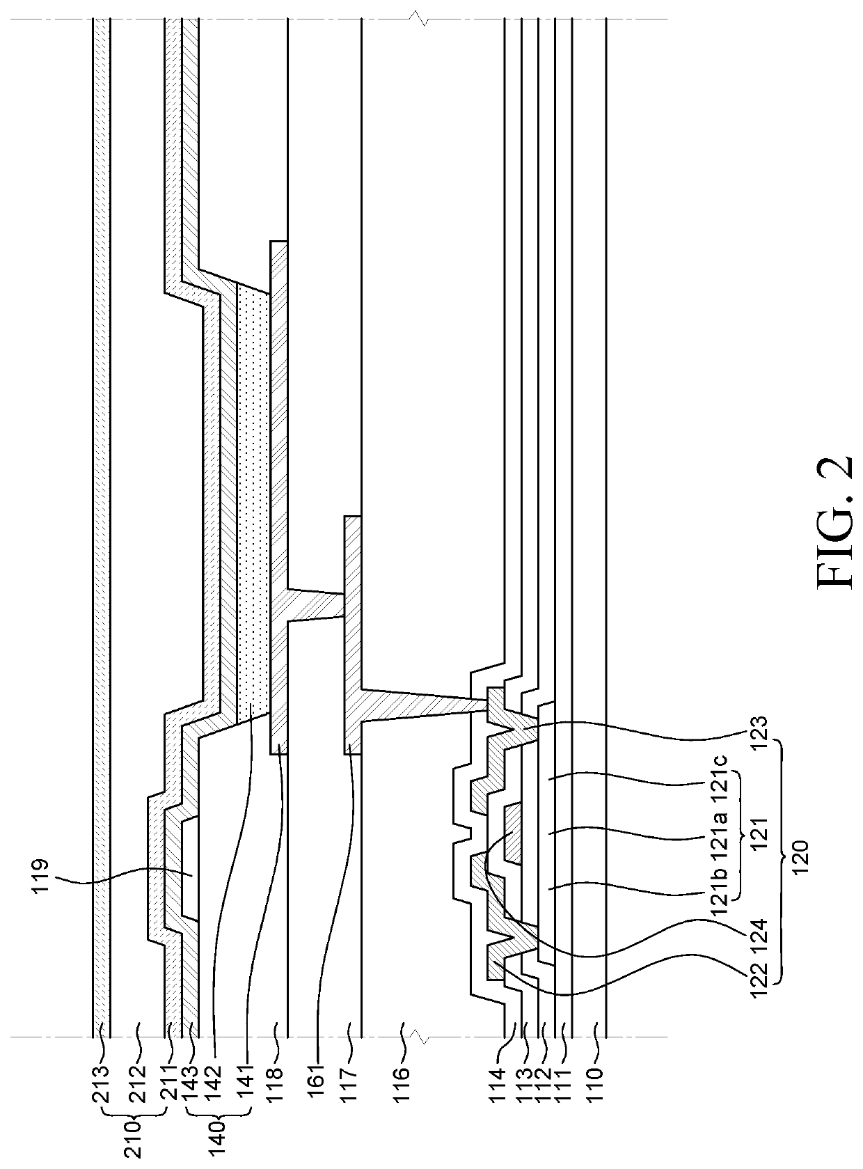
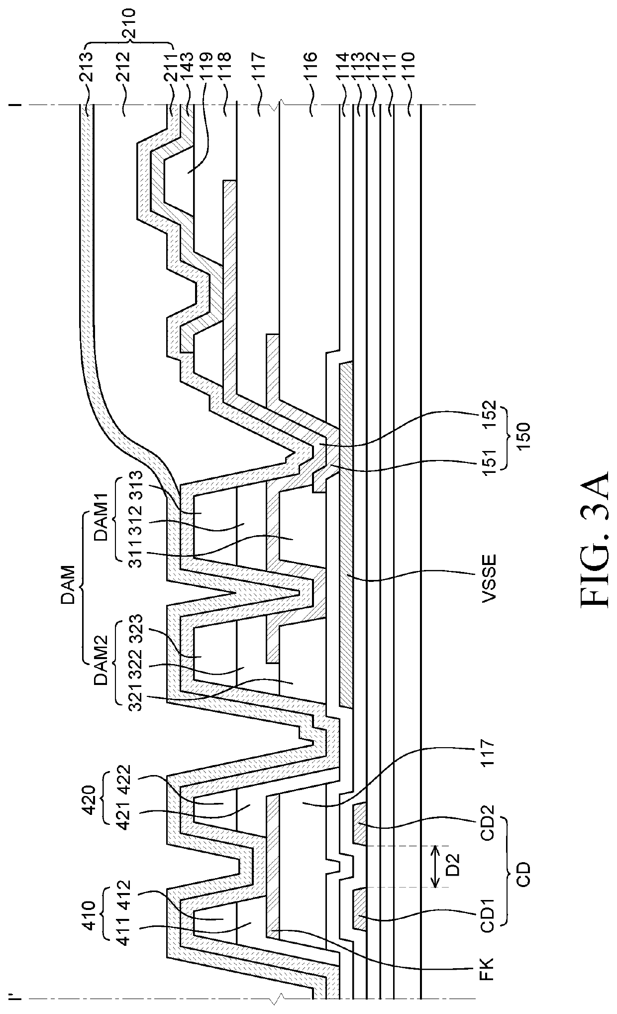
An electroluminescent display apparatus includes a substrate including a display area and a non-display area which surrounds the display area, a crack detecting unit on the substrate in the non-display area, an interlayer insulating layer disposed so as to cover the crack detecting unit, a power supply electrode which is located on the interlayer insulating layer and is disposed between the crack detecting unit and the display area, a protective layer disposed so as to cover the power supply electrode; a planarizing layer which is located on the protective layer and is disposed so as to overlap the crack detecting unit, and an alignment reference unit which is located on the planarizing layer and overlaps the crack detecting unit.

Description

CROSS-REFERENCE TO RELATED APPLICATIONS[0001]This application claims the benefit of Republic of Korea Patent Application No. 10-2018-0173270 filed on Dec. 31, 2018, which is incorporated herein by reference.BACKGROUNDField of Technology[0002]The present disclosure relates to an electroluminescent display apparatus.Description of the Related Art[0003]Currently, as it enters a full-scale information era, a field of a display apparatus which visually expresses electrical information signals has been rapidly developed and studies are continued to improve performances of various display apparatuses such as a thin thickness, a light weight, and low power consumption. A representative example of the display apparatus may include a liquid crystal display device (LCD), an electroluminescent display device, and a micro-LED display device.[0004]The electroluminescent display apparatus is a self-emitting display apparatus so that a separate light source is not necessary, which is different from...

Claims


Application Information

Patent Timeline
IPC IPC(8): H01L51/52H01L27/32G09G3/00
CPCH01L27/3246H01L27/3258H01L27/3276H01L51/5253G09G3/006H10K59/873H10K59/131G09G3/3208G09G2300/0426H10K59/122H10K59/124H10K59/1213H10K71/70H10K77/10H10K59/123H10K59/8051H10K59/8052H10K59/87H10K59/8791H10K50/844
Inventor KIM, TAERYONGMIN, TAEHYUN
Owner LG DISPLAY CO LTD
Learn More