
Management of communication between a terminal and a network server

a terminal and network server technology, applied in the field of communication system, communication system, connection management, etc., can solve the problems of inability to reach the application server, inability to communicate with the gateways of the desired loraTM network, and high cost of the gateway

Active Publication Date: 2020-07-02
ORANGE SA (FR)
View PDF14 Cites 2 Cited by
  • Summary
  • Abstract
  • Description
  • Claims
  • Application Information

AI Technical Summary

Benefits of technology

The patent describes a system where a terminal device can communicate with an application server using a network server. This means that the terminal doesn't have to be re-initialized when it's used again. The system also uses an inexpensive transmission device that doesn't require a wired or cellular connection. Instead, it communicates with one or more terminals and a network gateway through a radio link. This means that the transmission device consumes less energy, so it doesn't need to be plugged into an electric current socket. Instead, it can be powered by batteries or cells. This makes it easier to install.

Problems solved by technology

Despite a radio technology that is optimized for a long range, numerous terminals designed to operate according to the LoRa™ technology do not succeed in communicating with the gateways of the desired Lora™ network since the signals sent by these terminals do not reach the gateways.
However, these gateways are expensive.
This poses problems if the final place of installation is not situated in a zone of radio coverage of the gateway equipments of the LoRa network.
Therefore, they do not reach the application server.
When the terminal communicates with the network server via a transmission device, this initially configured lag might not be sufficient, for example to carry out a relaying of the messages.

Method used


Image

  • Management of communication between a terminal and a network server
  • Management of communication between a terminal and a network server
  • Management of communication between a terminal and a network server

Examples


first embodiment

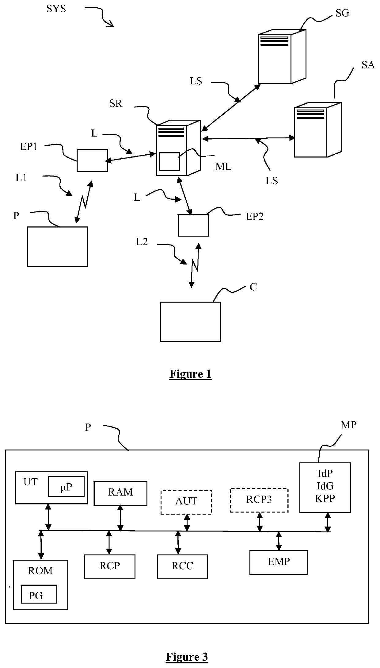
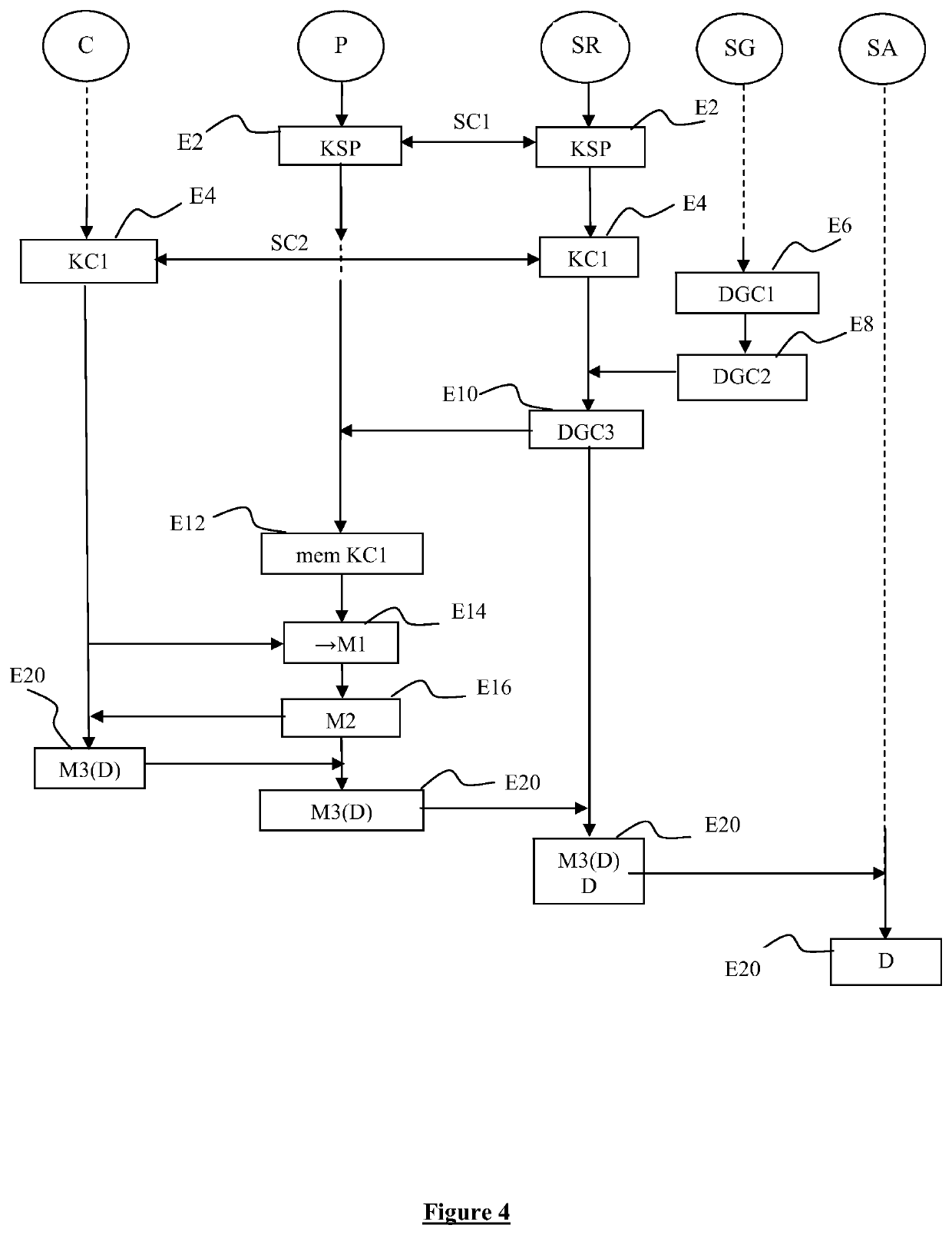
[0133]a management method implemented in the system SYS will now be described with reference to FIG. 4.

[0134]During a step E2, the transmission device P and the network server SR establish between themselves a communication session SC1.

[0135]The establishment of the communication session SC1 comprises the generation of a session key KSP on the one hand by the transmission device P and on the other hand by the network server SR.

[0136]The session key KSP is generated on the basis of the main key KPP.

[0137]Information relating to the established session SC1 is recorded in association with an identifier of the transmission device P by the network server SR in a memory accessible to the network server, for example in the list LT of the memory ML.

[0138]In a known manner, the establishment of the session SC1 allows the transmission device P to transmit data messages destined for the management server SG. The data messages contain an identifier IdP of the transmission device P, an identifie...

second embodiment

[0189]a management method implemented in the system SYS will now be described with reference to FIG. 5.

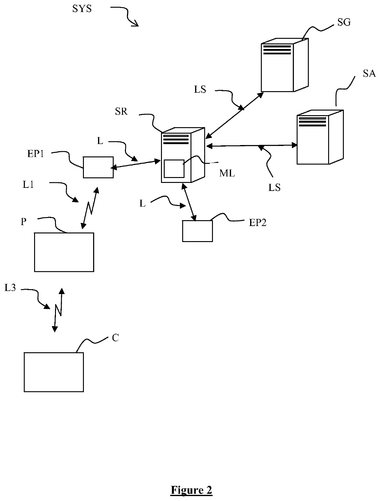
[0190]During a step S0, the authentication module AUT of the transmission device P transmits to the network server SR, a connection request DA1. The connection request DA1 is sent by the transmission device P, via the radio link L1. It is relayed to the network server SR by the gateway equipment EP1 via the link L.

[0191]The connection request DA1 contains the identifier IdP of the transmission device P, the identifier IdG of the management server SG with which the transmission device P is asking to be connected and a random value AL1 generated by the transmission device P.

[0192]The connection request DA1 is for example a message JoinRequest defined in the LoRaWAN™ standard.

[0193]During a step S2, subsequent to the reception of the request DA1, the transmission device P and the network server SR establish a communication session SC1.

[0194]The establishment of the communication link ...


PUM


Abstract

A management method implemented by a transmission device capable of communicating via a radio link with a piece of gateway equipment of a telecommunications network and configured for communicating with a network server of the network. The method includes: receiving a management request of a terminal capable of communicating via the radio link with a piece of gateway equipment of the network and having established a communication session with the network server, at least one session key being shared between the terminal and the network server, the management request containing an identifier of the terminal and the session key; intercepting, following reception of the management request, at least one message sent by the terminal; and transmitting, in response to the message, at least one response message encrypted with the session key received. A transmission device implementing the method is also provided.

Description

CROSS-REFERENCE TO RELATED APPLICATIONS[0001]This application is a Section 371 National Stage Application of International Application No. PCT / FR2018 / 052037, filed Aug. 8, 2018, the content of which is incorporated herein by reference in its entirety, and published as WO 2019 / 030457 on Feb. 14, 2019, not in English.FIELD OF THE DISCLOSURE[0002]The invention lies in the field of telecommunications.[0003]The invention relates more particularly to a communication system in which a terminal communicates with an application server able to provide application services to this terminal by way of a telecommunications network, and more particularly of a server of this network. No limitation is attached to the nature of the terminal or to the nature of the application services provided. The terminal can be a fixed or mobile terminal, such as an electric meter, a sensor, etc. The application server can be operated by any provider of services, such as for example an electricity provider, water ...

Claims


Application Information

Patent Timeline
Patent Type & Authority Applications(United States)
IPC IPC(8): H04L29/08H04W76/10H04L12/66H04L9/32H04L29/06
CPCH04L9/32H04W76/10H04W84/18H04L12/66H04L67/141H04L63/061H04W88/16H04L67/146H04L67/125H04W12/04H04W4/70H04W76/14H04W12/37
Inventor LAMPIN, QUENTIN
Owner ORANGE SA (FR)
Learn More