
Fluid temperature control installation for rotorcraft, associating a system for cooling a power plant with a system for heating a cabin

a technology for rotorcraft and installation of flue temperature control, which is applied in the field of rotorcraft, can solve the problems of significant loss of energy in cruising flight situation, drawbacks of cooling system for rotorcraft, and loss of energy in other directions, and achieves the effect of reducing the overall energy needs of installation, and reducing the risk of damag

Active Publication Date: 2016-10-18
EUROCOPTER
View PDF6 Cites 1 Cited by
  • Summary
  • Abstract
  • Description
  • Claims
  • Application Information

AI Technical Summary

Benefits of technology

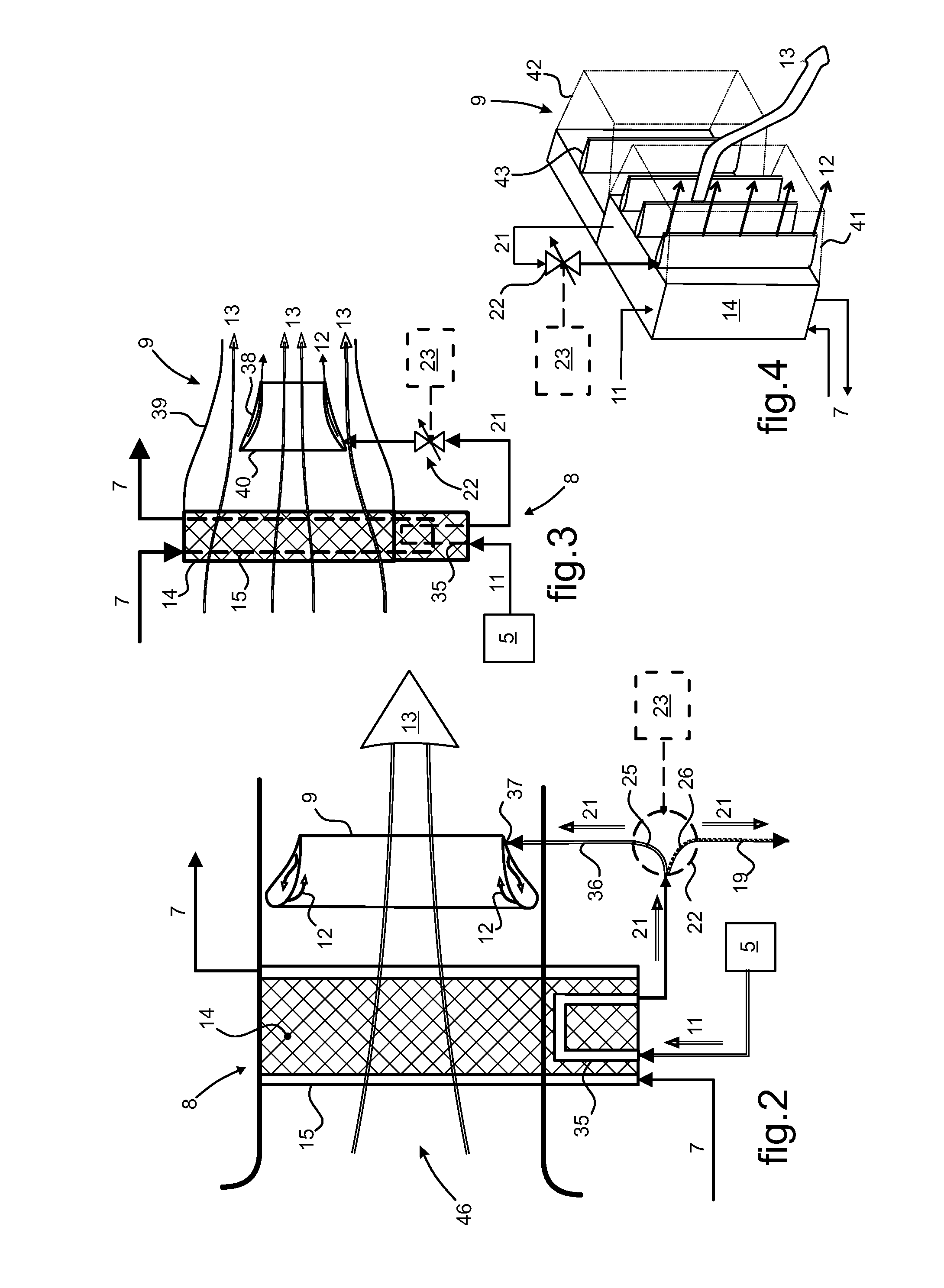
This patent seeks to create an installation that uses less energy, has a simple structure, and is reliable and safe. Specifically, the invention is a bladeless ventilator made up of multiple modules that can be easily adapted to different heat exchange structures, such as an aircraft. Each module contains at least one elongate air ejector, which allows for flexibility in the size of the heat exchanger and ensures efficient cooling of the fluid circulating in the closed circuit.

Problems solved by technology

The use of such cooling systems for a rotorcraft present drawbacks, in particular in terms of energy losses and difficulties associated with safe installation on board the rotorcraft.
This leads to energy being lost in other situations in which the rotorcraft might be placed, given that the airflow generator member is driven so as to consume a constant level of power.
This leads to significant loss of energy in a cruising flight situation and / or in a situation where temperatures outside the rotorcraft are low.
The proximity between the airflow generator member and the main gearbox makes it difficult to install the airflow generator member in a zone of the rotorcraft that houses power members, with constraints in terms of safety and making the operation of the airflow generator member reliable.
The use of various cabin air temperature control systems presents drawbacks, in particular in terms of energy losses, sound nuisance, and / or difficulties associated with installing such systems safely in the rotorcraft.
Also by way of example, for air temperature control systems using hot air produced by the main power plant, these lead in particular to sound nuisance and to difficulties of safe incorporation in the rotorcraft.
Safe incorporation of ducts for conveying hot air from the main compressor to the temperature control device is difficult.

Method used


Image

  • Fluid temperature control installation for rotorcraft, associating a system for cooling a power plant with a system for heating a cabin
  • Fluid temperature control installation for rotorcraft, associating a system for cooling a power plant with a system for heating a cabin
  • Fluid temperature control installation for rotorcraft, associating a system for cooling a power plant with a system for heating a cabin

Examples


Embodiment Construction

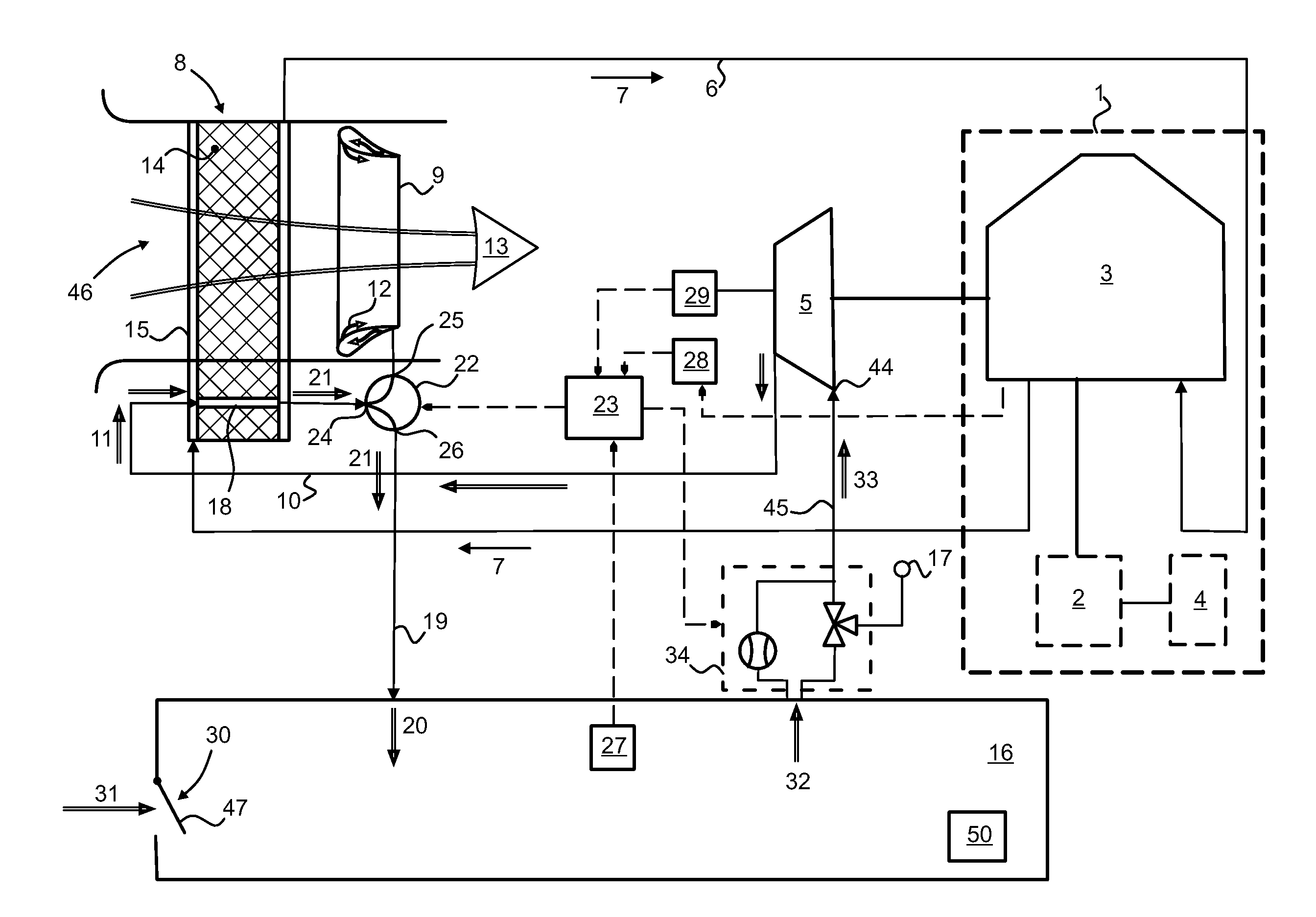
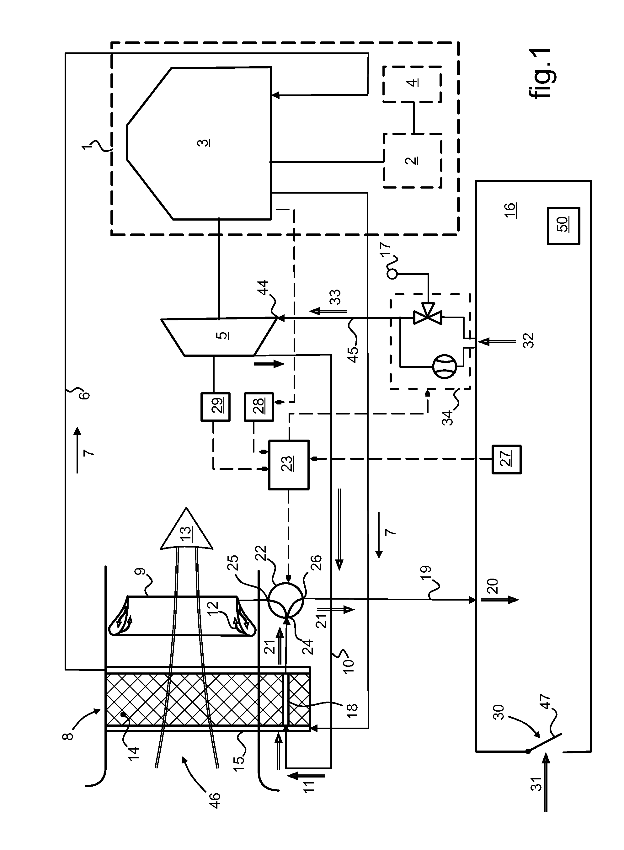
[0090]In FIG. 1, an aircraft, and more particularly a rotorcraft, is fitted with a main power plant 1 for driving at least one rotor, and is fitted with a fluid temperature control installation. The main power plant 1 has at least one main engine 2 engaged with a main gearbox (MGB) 3. In the example shown, the main engine 2 is a turboshaft engine having a main compressor 4.

[0091]An accessory compressor 5 is driven by the MGB 3 and has an air inlet 44 in air-flow communication with a third air circuit 45. The accessory compressor 5 is a member producing the energy needed for operating the entire fluid temperature control installation fitted to the rotorcraft.

[0092]The rotorcraft has at least one system for cooling at least one member for cooling, including the main gearbox (MGB) 3. The cooling system comprises:

[0093]a closed circuit 6 for circulating a fluid for cooling 7, the closed circuit 6 including at least one heat exchanger 8 fitted with a bladeless ventilator 9; and

[0094]a fi...


PUM


Abstract

A fluid temperature control installation for a rotorcraft, the installation comprising a system for cooling a main transmission (3) and a system for temperature control of the ambient air (32) of a cabin (16). A heat exchanger (8) is fitted with a bladeless ventilator (9). A source air stream (11) generated by an accessory compressor (5) driven by the main transmission (3) passes through the heat exchanger (8) where it takes heat. The source air stream (11) is distributed selectively to the bladeless ventilator (9) to generate a cooling air stream (13) passing through the heat exchanger (8), and / or is distributed to the cabin (16) after passing through the heat exchanger (8) in order to heat the ambient air (32) of the cabin.

Description

CROSS REFERENCE TO RELATED APPLICATIONS[0001]This application claims priority to French patent application No. FR 12 00191 filed on Jan. 24, 2012, the disclosure of which is incorporated in its entirety by reference herein.BACKGROUND OF THE INVENTION[0002](1) Field of the Invention[0003]The present invention lies in the field of fluid temperature control installations on board aircraft, and more particularly rotorcraft. Taken generally, such installations comprise a variety of systems for applying temperature control to a fluid, in particular a system for cooling a main power plant of the rotorcraft and a system for temperature control of air inside the cabin of the rotorcraft.[0004](2) Description of Related Art[0005]Aircraft are fitted with a fluid temperature control installation that is made of various systems for controlling the temperature of a fluid, which systems are dedicated to respective particular functions. Overall, the installation should be considered as grouping toge...

Claims


Application Information

Patent Timeline
Patent Type & Authority Patents(United States)
IPC IPC(8): F25B27/00B64D13/08B64D13/06F25B9/06F25B19/02
CPCB64D13/08B64D13/06B64D2013/0648B64D2013/0674F25B9/065F25B19/02F25B2309/005Y02T50/56Y02T50/50
Inventor POMME, VINCENT
Owner EUROCOPTER
Learn More