
Fluid transfer Apparatus and related methods

a technology of liquid transfer apparatus and transfer device, which is applied in the directions of packaging, closures, transportation and packaging, etc., can solve the problems of difficult dispense of liquid detergent, excessive use of liquid detergent, and difficulty in measuring the correct amount of liquid detergent, so as to avoid accidental drop of liquid from the container, easy to draw from the container, and easy to put back into the container

Inactive Publication Date: 2020-07-16
NEGAARD II KENNETH WAYNE
View PDF0 Cites 2 Cited by
  • Summary
  • Abstract
  • Description
  • Claims
  • Application Information

AI Technical Summary

Benefits of technology

The present invention is a fluid transfer apparatus that has several technical effects. Firstly, it allows for easy drawing of liquid from a container without tilting it. Secondly, the liquid can be controlled during the transfer. Thirdly, any excess liquid can be easily put back into the container. Fourthly, it prevents spillage from accidentally dropped containers. Lastly, the fluid transfer apparatus is economical to manufacture and easy to use.

Problems solved by technology

Despite, the liquid detergents having an edge over powder-based detergents, the liquid detergents are difficult to dispense.
Measuring the correct amount of liquid detergents is often difficult and leads to using an excess amount of liquid detergents.
The use of an excessive amount of liquid laundry detergents is not only an economical shortcoming but also wastage of resources.
Also using more than the recommended amount of detergent does not increase the cleaning efficiency but may lead to stains on clothes.
However, measuring a liquid with the available measuring cups is often difficult.
Particularly, pouring the liquid detergent into the measuring cap can be difficult and may lead to spillage of the liquid detergent.
Thus, the user may end up adding an excessive amount of the liquid detergent.

Method used


Image

  • Fluid transfer Apparatus and related methods
  • Fluid transfer Apparatus and related methods
  • Fluid transfer Apparatus and related methods

Examples


Embodiment Construction

[0020]Subject matter will now be described more fully hereinafter with reference to the accompanying drawings, which form a part hereof, and which show, by way of illustration, specific exemplary embodiments. Subject matter may, however, be embodied in a variety of different forms and, therefore, covered or claimed subject matter is intended to be construed as not being limited to any exemplary embodiments set forth herein; exemplary embodiments are provided merely to be illustrative. Likewise, a reasonably broad scope for claimed or covered subject matter is intended. Among other things, for example, the subject matter may be embodied as methods, devices, components, or systems. The following detailed description is, therefore, not intended to be taken in a limiting sense.

[0021]The word “exemplary” is used herein to mean “serving as an example, instance, or illustration.” Any embodiment described herein as “exemplary” is not necessarily to be construed as preferred or advantageous ...


PUM


Abstract

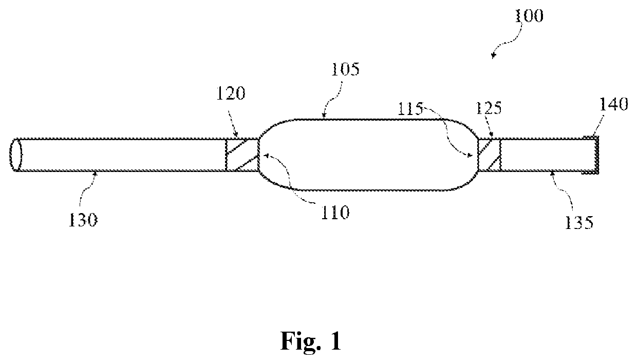
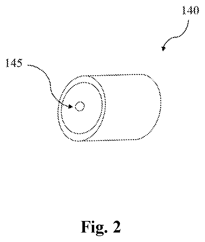
The present invention is directed to a fluid transfer apparatus for sucking liquid from a container and transferring to another container or target. The fluid transfer apparatus comprising a squeeze bulb, the squeeze bulb having a first opening and an opposite second opening. A first check valve coupled to the first opening and a second check valve coupled to the second opening, wherein the first check valve and the second check valve together are configured to control the direction of fluid flow in one direction i.e. the liquid can enter from first check valve leaves from the second check valve. A transfer tube is fluidly coupled to the first check valve and a dispensing tube is coupled to the second check valve. The squeeze bulb is configured to suck liquid from a container through the transfer tube, wherein the liquid collects in the squeeze bulb and the dispensing tube. The other end of the dispensing tube is closed by a nipple, the nipple having a hole.

Description

FIELD OF INVENTION[0001]The present invention relates to a fluid transfer apparatus, and more particularly, to an apparatus for sucking fluid from a container for transferring to a target.BACKGROUND[0002]Laundry is one of the requisite daily chores of a person. According to an article written by thespruce.com, the average family in the United States of America does close to ten loads of laundry a week. The laundry detergent is an indispensable part of laundry and various formulation of the laundry detergent is available commercially. Liquid laundry detergents are quite popular because of their one or more advantages. The advantages of liquid laundry detergents include completely dissolving in liquid and the detergent does not accumulate on woolen fibers. Despite, the liquid detergents having an edge over powder-based detergents, the liquid detergents are difficult to dispense. Measuring the correct amount of liquid detergents is often difficult and leads to using an excess amount of...

Claims


Application Information

Patent Timeline
IPC IPC(8): B65D47/20B65D47/32B65D47/12
CPCB65D47/2056B65D47/122B65D47/32B65D25/48
Inventor NEGAARD, II, KENNETH WAYNE
Owner NEGAARD II KENNETH WAYNE
Learn More