
Wet friction plate

a technology of friction plate and wet friction, which is applied in the direction of friction clutches, braking elements, clutches, etc., can solve the problems of deterioration of fuel consumption of vehicles, and achieve the effect of reducing drag torque more effectively

Inactive Publication Date: 2020-07-16
FCC KK
View PDF0 Cites 0 Cited by
  • Summary
  • Abstract
  • Description
  • Claims
  • Application Information

AI Technical Summary

Benefits of technology

This patent is about a wet friction plate used in a clutch device. The wet friction plate has a structure that promotes the separation between the clutch plate and the plate when it is rotating, reduces the drag torque and reduces the amount of lubricating oil needed. This is achieved by forming ride-on sides and a ride-on groove on the inner and outer edges of the friction material. Additionally, the wet friction plate is designed with a notch groove on the outer edge of the friction material and chamfered outer corner portions on the outer peripheral edge portion. These features work together to significantly reduce the drag torque compared to a wet friction plate without these features.

Problems solved by technology

The drag torque causes deterioration of fuel consumption of the vehicle.

Method used


Image

  • Wet friction plate
  • Wet friction plate
  • Wet friction plate

Examples


Embodiment Construction

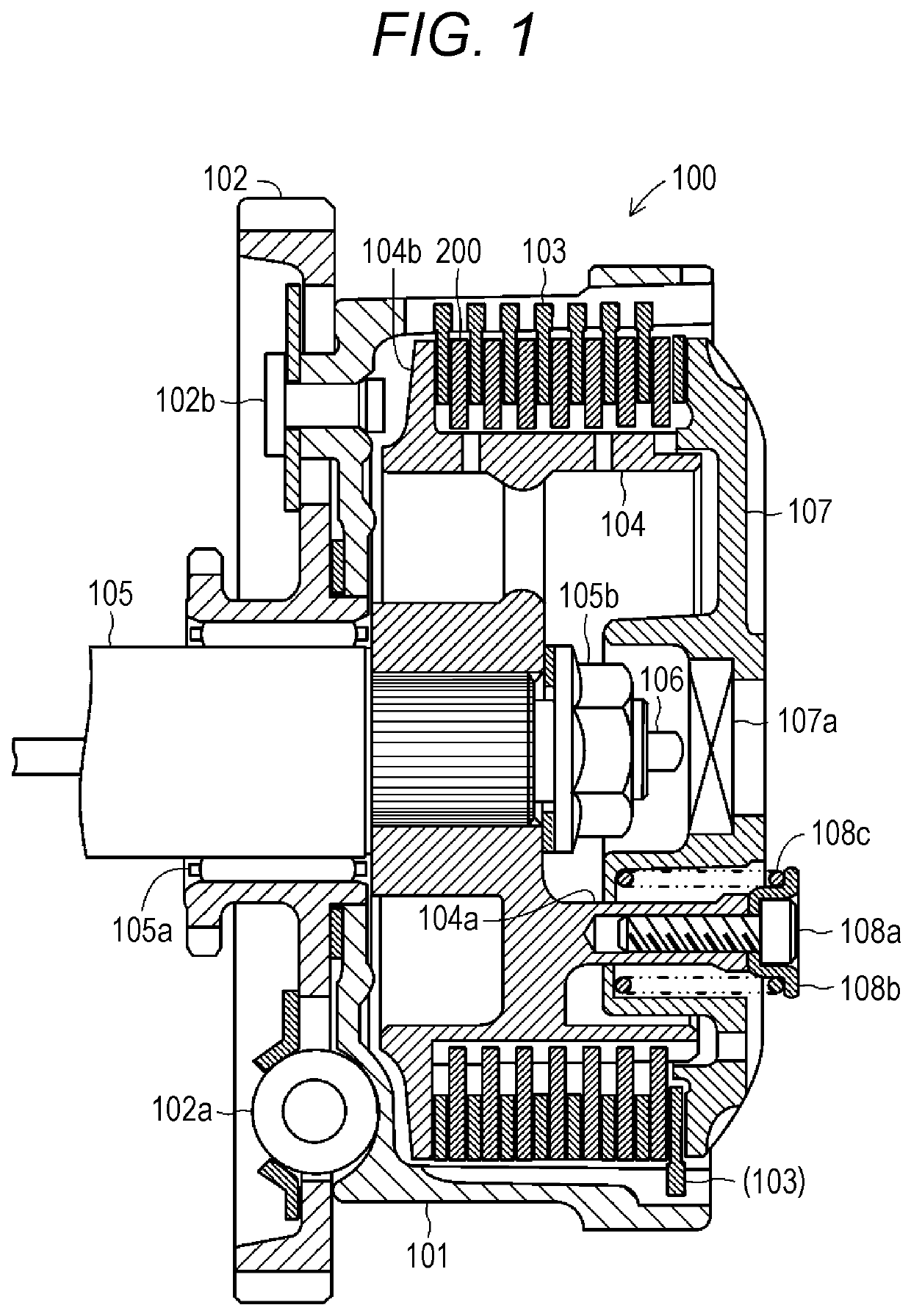
[0033]Hereinafter, an embodiment of a wet friction plate according to the present invention will be described with reference to the drawings. FIG. 1 is a cross-sectional view showing an outline of an overall configuration of a multi-plate clutch device 100 including a wet friction plate 200 according to the present invention. In the drawings referred to in the present specification, some of components are shown schematically, for example, exaggerated in order to facilitate understanding of the present invention. For this reason, dimension, ratio or the like between the components may differ. The multi-plate clutch device 100 is a mechanical device for transmitting or blocking a driving force of an engine (not shown) that is a prime mover in a two-wheeled vehicle (motorcycle) to a wheel (not shown) that is a driven body. The multi-plate clutch device 100 is disposed between the engine and a transmission (not shown).

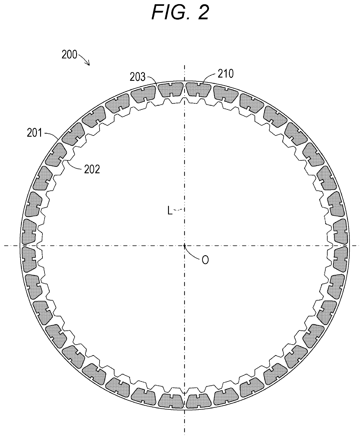
(Configuration of Wet Friction Plate 200)

[0034]The multi-plate clutch...


PUM


Abstract

Provided is a wet friction plate capable of further reducing drag torque. A wet friction plate 200 is configured to include an oil groove 203 and a friction material 210 on a flat plate annular core metal 201. The friction material 210 is formed with ride-on sides 214a, 214b and a ride-on groove 215. The ride-on sides 214a and 214b respectively extend linearly between an inner peripheral edge portion 211 formed on an inner side in a radial direction of the core metal 201 and two circumferential end portions 213a, 213b respectively extending in the radial direction at both end portions in a circumferential direction of the core metal 201. The ride-on groove 215 extends in a concave shape toward an outer side in the radial direction of the core metal 201 at a central portion of the inner peripheral edge portion 211 in the circumferential direction of the core metal 201. Further, the ride-on sides 214a and 214b are respectively formed to extend in a direction away from an imaginary oil groove center line L from the circumferential end portions 213a and 213b toward the inner peripheral edge portion 211.

Description

TECHNICAL FIELD[0001]The present invention relates to a wet friction plate used in oil. Specifically, the present invention relates to the wet friction plate suitable for a multi-plate clutch device that is disposed between a prime mover and a driven body rotationally driven by the prime mover, and transmits or blocks a driving force of the prime mover to the driven body.BACKGROUND ART[0002]Conventionally, vehicles such as a four-wheeled vehicle and a two-wheeled vehicle are equipped with the multi-plate clutch device in order to transmit or block a rotational driving force of the prime mover such as an engine to the driven body such as a wheel. In general, in the multi-plate clutch device, two plates arranged opposite to each other in lubricating oil, specifically, the wet friction plate having a friction material provided on a surface of a flat plate annular core metal, and a clutch plate having no friction material are pressed against each other to transmit or brake the rotationa...

Claims


Application Information

Patent Timeline
Patent Type & Authority Applications(United States)
IPC IPC(8): F16D13/74F16D13/64F16D65/12F16D13/72
CPCF16D2065/1324F16D13/74F16D13/72F16D2065/1328F16D65/128F16D13/648F16D65/122F16D55/24F16D65/186F16D2069/004F16D13/62F16D55/36
Inventor MIYAGAWA, MASATOSHIFUJIWARA, HIROMIINOUE, NAOFUMI
Owner FCC KK
Learn More