Clamp

a technology of clamping and counter-members, applied in the direction of rod connection, sleeve/socket joint, etc., can solve the problems of troublesome clamping of the members together, easy bending of straight corresponding sections, and troublesome work of attaching the clamping to the counter-members. , to achieve the effect of less bending

Active Publication Date: 2020-07-16
TOGO SEISAKUSYO CORP
View PDF0 Cites 0 Cited by
  • Summary
  • Abstract
  • Description
  • Claims
  • Application Information

AI Technical Summary

Benefits of technology

[0007]According to one aspect of the present disclosure, a clamp serves to fasten a tubular connecting member covered to a counter member by the elastic restoring force of the clamp itself. The clamp includes an annular clamp body with opposite ends intersecting, and a pair of tabs projecting radially outward from the opposite ends of the clamp body. The counter member has a tubular outer contour including at least on...

Problems solved by technology

Therefore, the work of attaching the clamp to the counter member is troublesome.
It is also troublesome to clamp the members together even if the clamp has a wire clamp or a worm thread clamp, instead of using the ring member.
Therefore, when enlarging the diameter of the clamp body by pinching the pair of tabs, the straight corresponding sections ar...

Method used


Image

  • Clamp
  • Clamp
  • Clamp

Examples


Embodiment Construction

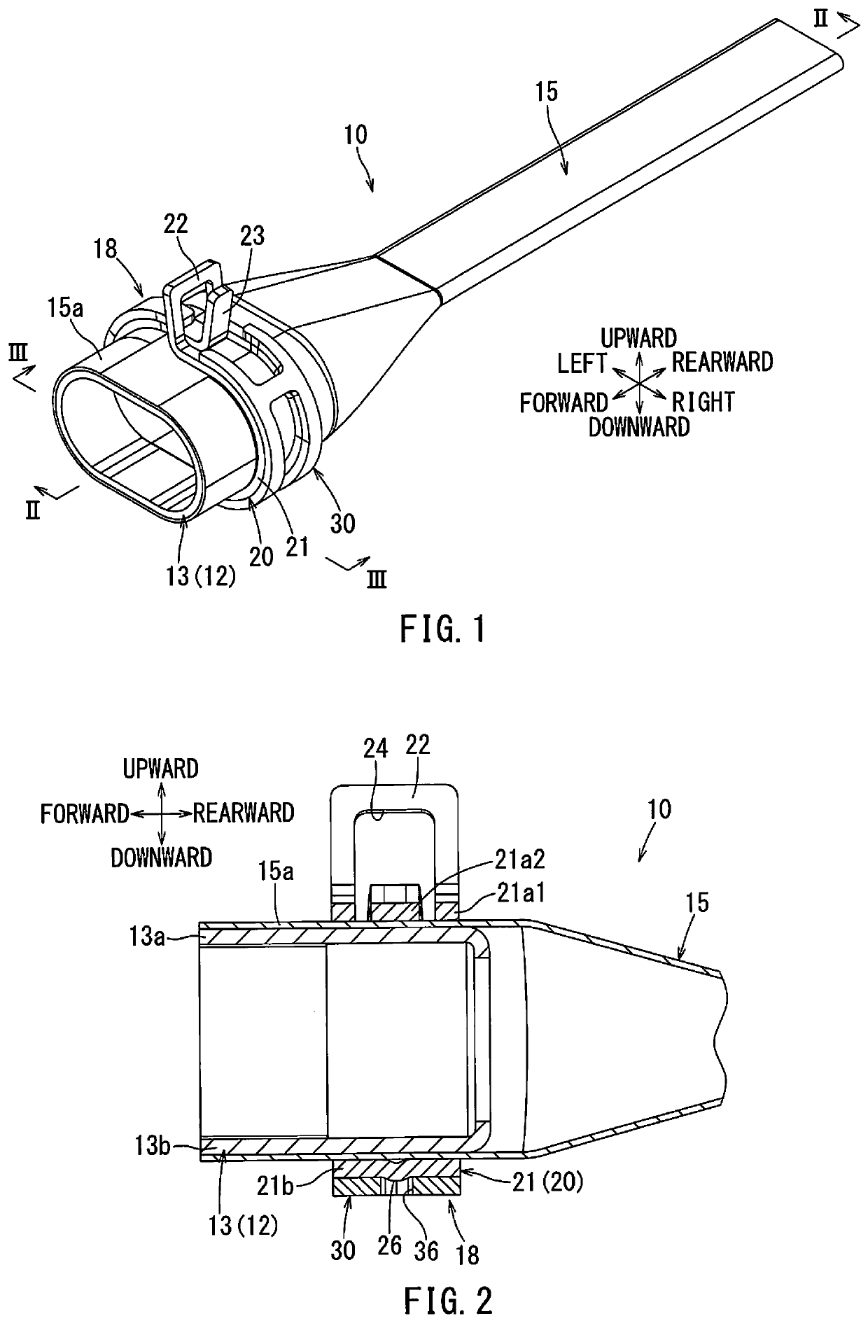
[0032]As shown in FIGS. 1 to 3, a clamp according to a first embodiment may be used as part of a shield connector or the like. Although directions concerning the clamp are indicated by arrows in each of the drawings for the convenience of explanation, these directions are not intended to necessitate an orientation direction of the clamp.

[0033]As shown in FIG. 1, the shield connector 10 includes a shield shell 12, a shield member 15, and a clamp 18. The shield shell 12 is made of metal and has a tubular portion 13. The tubular portion 13 has an elongated cylindrical shape. The shield connector 10 may be used to cover a connector portion (not shown) of a high-voltage wire harness.

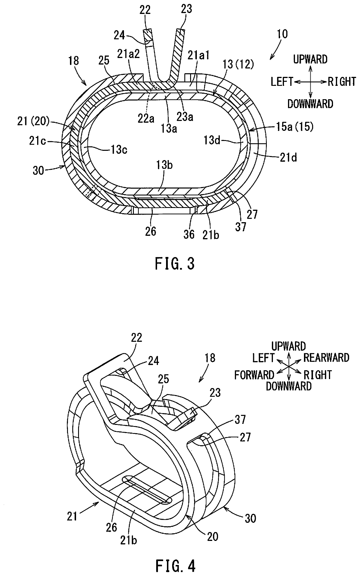
[0034]As shown in FIG. 3, the tubular portion (which is an embodiment of a counter member) 13 of the shield shell 12 has a rectangular shape with rounded corners. The tubular portion is comprised of two straight shape sections (which are embodiments of straight sections) 13a, 13b and two curved shape sections...


PUM


Abstract

A clamp serves to fasten a shield member to a tubular portion of a shield shell using the elastic restoring force of the clamp. The clamp includes an annular clamp body and a pair of tabs. The tubular portion includes a tubular outer contour having two straight sections and two curved sections in a cross-sectional view. The clamp body includes a straight corresponding section corresponding to one of the straight section of the tubular portion and curved corresponding sections corresponding to the curved sections. The straight corresponding section is configured to bend less easily than the curved corresponding sections.

Description

CROSS-REFERENCE TO RELATED APPLICATIONS[0001]The present application is a U.S. National Phase entry of, and claims priority to, PCT Application No. PCT / JP2018 / 020179, filed May 25, 2018, which claims priority to Japanese Patent Application No. 2017-157528, filed Aug. 17, 2017, both of which are incorporated herein by reference in their entireties for all purposes.BACKGROUND[0002]The present disclosure relates to a clamp. More particularly, it relates to a clamp which fastens a tubular connecting member to a counter member using the elastic restoring force of the clamp itself. For example, the clamp includes an annular clamp body with opposite ends intersecting each other, and a pair of tabs projecting radially outward from the opposite ends of the clamp body.[0003]A counter member generally has, for example, an elongated cylindrical outer contour having a rectangular shape with rounded corners. The elongated cylindrical outer contour comprises two straight sections and two curved se...

Claims


Application Information

Patent Timeline
IPC IPC(8): F16L21/06
CPCF16L21/06F16B2/20F16B2/24F16B7/04F16L33/03
Inventor IWAFUNE, TAKAHIRO
Owner TOGO SEISAKUSYO CORP
Why Eureka
Try Eureka