Method for representing the surroundings of a vehicle

a vehicle and surroundings technology, applied in scene recognition, instruments, transportation and packaging, etc., can solve the problems of vehicle encompassing surround view system driver not being able to recognize hazards, risk of vehicle colliding with obstacles, and in principle collision risk, so as to avoid collision risk

Active Publication Date: 2020-07-16
ROBERT BOSCH GMBH
View PDF0 Cites 2 Cited by
  • Summary
  • Abstract
  • Description
  • Claims
  • Application Information

AI Technical Summary

Benefits of technology

[0003]An example method according to the present invention may permit a rapid and reliable detection of hazardous situations due to the vehicle approaching an obstacle. This is achieved due to the fact that, in addition to a first display, which provides the driver with an overview of the surroundings, a second depiction is displayed, which alerts the driver specifically to the risk of the approaching obstacle.
[0009]In one alternative embodiment of the present invention, it is provided that the first depiction represents an image from a virtual perspective of a three-dimensional model of the surroundings, while the second depiction schematically represents a distance between vehicles and an obstacle, which the vehicle is approaching. The second depiction advantageously includes no textures. Therefore, the image of the first depiction is designed to be highly detailed, since, in particular, textures are utilized for visualizing the representation of the surroundings. A merely schematic approach is utilized for the second depiction, however. This may take place, in particular, due to the fact that a maximum detection range of the surroundings sensors is schematically displayed around a representation of the vehicle, the area in which the surroundings sensors have detected obstacles being appropriately characterized. Alternatively, the detected outer edges of the obstacles may also be represented by appropriate lines, in order to implement the second display. In this way, the distance to the obstacle is immediately made clear to the driver of the vehicle, so that the driver may initiate appropriate driving maneuvers in order to avoid a collision between the vehicle and the obstacle.
[0010]In one further alternative, the first depiction and the second depiction are separate depictions. This has the advantage that the first depiction remains unchanged, while the second depiction takes place merely in order to emphasize aforementioned approaches of the vehicle to an obstacle. Due to the separate representation, it is also made possible, in particular, to appropriately visualize multiple spots at which the vehicle approaches an obstacle. This is advantageous, in particular, during parking processes, when the vehicle approaches at a plurality of areas the proximity of obstacles, i.e., other parking vehicles and / or boundary walls.
[0015]Finally, the present invention relates to a control unit for a vehicle. The control unit encompasses at least one interface for the connection of surroundings sensors. In addition, a display device may be connected to the interface. Therefore, the control unit is capable, in particular, of actuating the surroundings sensors in order to detect the surroundings of the vehicle and in order to ascertain obstacles in the surroundings of the vehicle. The control unit is therefore advantageously configured for running a computer program product of the type described above, or for carrying out a method as described above. The control unit may therefore provide a driver of the vehicle with assistance during the navigation of the vehicle through surroundings including obstacles, in order to thus avoid a risk of collisions between the vehicle and the obstacles.

Problems solved by technology

In the process, there is a risk, due to the large amount of pieces of information, that the driver of a vehicle encompassing a surround view system will not recognize hazards in a timely manner, such as the approach by the vehicle to an obstacle.
Moreover, an establishment of an approach by the vehicle to an ascertained obstacle takes place due to the fact that a predefined distance to the obstacle has been undershot.
As a result, there is a risk, in principle, of the vehicle colliding with the obstacle.
If the first depiction is not represented on the display device in such a way that it occupies the entire display device, then such a scaling is also unnecessary.

Method used


Image

  • Method for representing the surroundings of a vehicle
  • Method for representing the surroundings of a vehicle
  • Method for representing the surroundings of a vehicle

Examples


Embodiment Construction

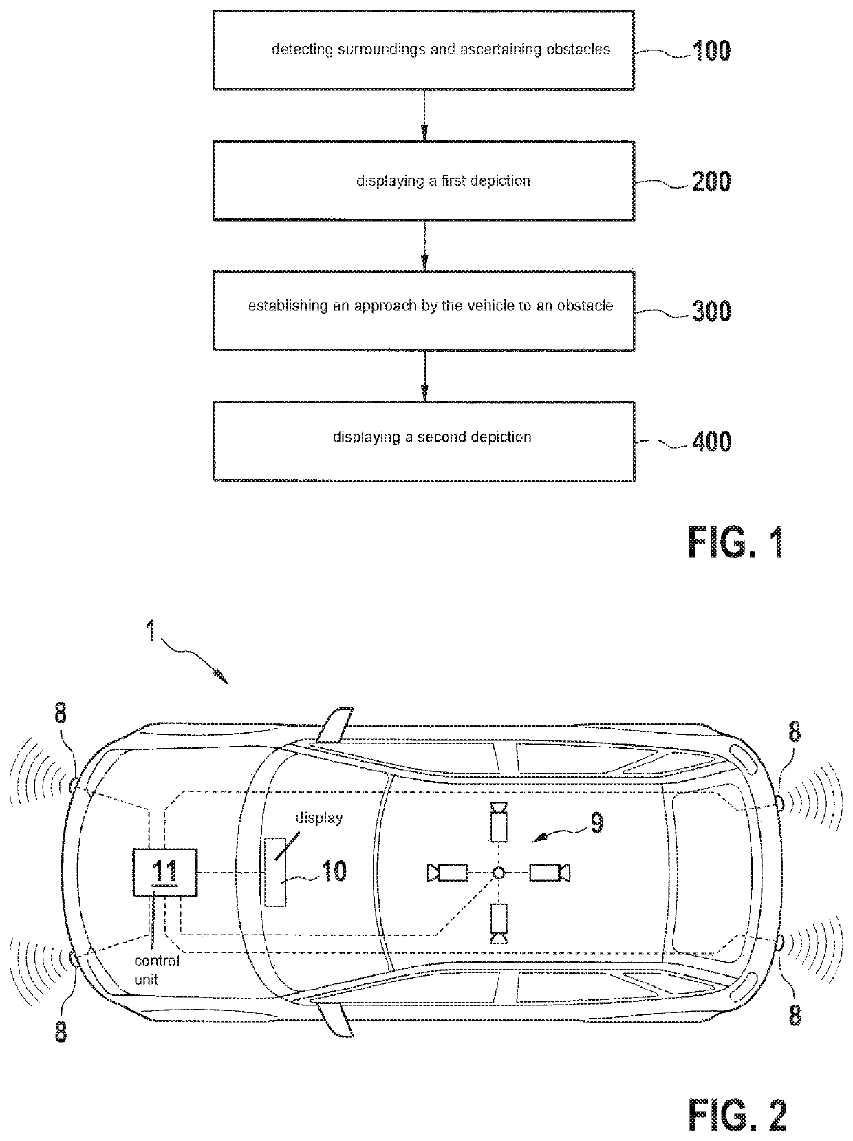
[0025]FIG. 1 schematically shows a flow chart of a method according to one exemplary embodiment of the present invention. The flow chart includes the steps of detecting the surroundings and ascertaining obstacles 100, of displaying a first depiction 200, of establishing an approach by the vehicle to an obstacle 300, and of displaying a second depiction 400. These steps are explained in the following, reference being made to vehicle 1, shown in FIG. 2, encompassing a control unit 11. Control unit 11 is utilized for carrying out the method shown in FIG. 1, control unit 11 being connected to a display device 10. Therefore, control unit 11 may prompt display device 10 to display depictions. In addition, control unit 11 is connected to surroundings sensors 8, 9, surroundings sensors 8, 9 encompassing ultrasonic sensors 8 and a camera system 9. With the aid of camera system 9, in particular, a three-dimensional detection of the surroundings of vehicle 1 is made possible. With the aid of u...


PUM


Abstract

A method for representing the surroundings of a vehicle. The method includes: detecting the surroundings of the vehicle and ascertaining obstacles in the surroundings with the aid of surroundings sensors of the vehicle; displaying a first depiction encompassing a representation of the surroundings including the obstacles and a representation of the vehicle on a display device; establishing an approach by the vehicle to an ascertained obstacle due to the fact that a predefined distance to the obstacle has been undershot; and displaying a second depiction including a detail, enlarged in comparison to the first depiction, of the representation of the surroundings including the obstacles and the representation of the vehicle on the display device, the detail representing the area of the surroundings and of the vehicle at which the approach by the vehicle to the obstacle was established.

Description

FIELD[0001]The present invention relates to a method for representing the surroundings of a vehicle, in particular for displaying obstacles in the surroundings of the vehicle. Moreover, the present invention relates to a computer program product for carrying out such a method. Finally, the present invention relates to a control unit for a vehicle, which is designed for carrying out such a method, in particular for running a computer program product.BACKGROUND INFORMATION[0002]Conventional systems may display to the driver a graphic representation of the surroundings of his / her vehicle. Such systems are also referred to as surround view systems (SVS). In such surround view systems, in particular, a combination of a plurality of different sensor signals takes place, which are all displayed to the driver, so that a maximum amount of information may be provided to the driver. These pieces of information are ascertained, for example, from signals of video sensors, radar sensors, LIDAR se...

Claims


Application Information

Patent Timeline
Patent Type & Authority Applications(United States)
IPC IPC(8): G06T15/20G08G1/16G06K9/00G06T3/40B60R1/00
CPCG06T15/20G08G1/16B60R1/00G06T3/40G06K9/00805B60R2300/30B60R2300/20B60R2300/8093G08G1/168B60R2300/301B60R2300/806G06V20/58
Inventor PANKEY, CAINESPARZA GARCIA, JOSE DOMINGOCANO, RAPHAEL
Owner ROBERT BOSCH GMBH
Why Eureka
Try Eureka