Wireless power transmitting device

Active Publication Date: 2020-07-16
LG ELECTRONICS INC
View PDF0 Cites 4 Cited by
  • Summary
  • Abstract
  • Description
  • Claims
  • Application Information

AI Technical Summary

Benefits of technology

[0011]The present invention provides a wireless power transmitting device capable of efficien

Problems solved by technology

Disadvantages to such a terminal supplying method are that the cables or wires take up a lot of space, are not easy to tidy up, and pose a risk of breakage.
However, the temperature of a transmitter coil increases with increasing transmission power, and, there is a need to protect the user from overload due to heat generation, product burnout, explosion, etc., especially when charging

Method used


Image

  • Wireless power transmitting device
  • Wireless power transmitting device
  • Wireless power transmitting device

Examples


Embodiment Construction

[0024]Hereinafter, the embodiments of the present invention will be described in more details with reference to the drawings.

[0025]The suffixes “module”, “part”, and “section” of elements herein are used for convenience of description, and thus can be used interchangeably and do not have any distinguishable meanings or functions.

[0026]The terms including “first,”“second,” and the like can be used to describe various elements, but the elements are not limited by the terms. The terms, if any, are used for distinguishing between one element and other elements.

[0027]The term “comprises” or “has” described herein should be interpreted not to exclude presence or addition possibility of characteristics, numbers, steps, operations, constituent elements, parts, or combinations thereof described in the specification but to designate presence of one or more other characteristics, numbers, steps, operations, constituent elements, parts, or combinations thereof.

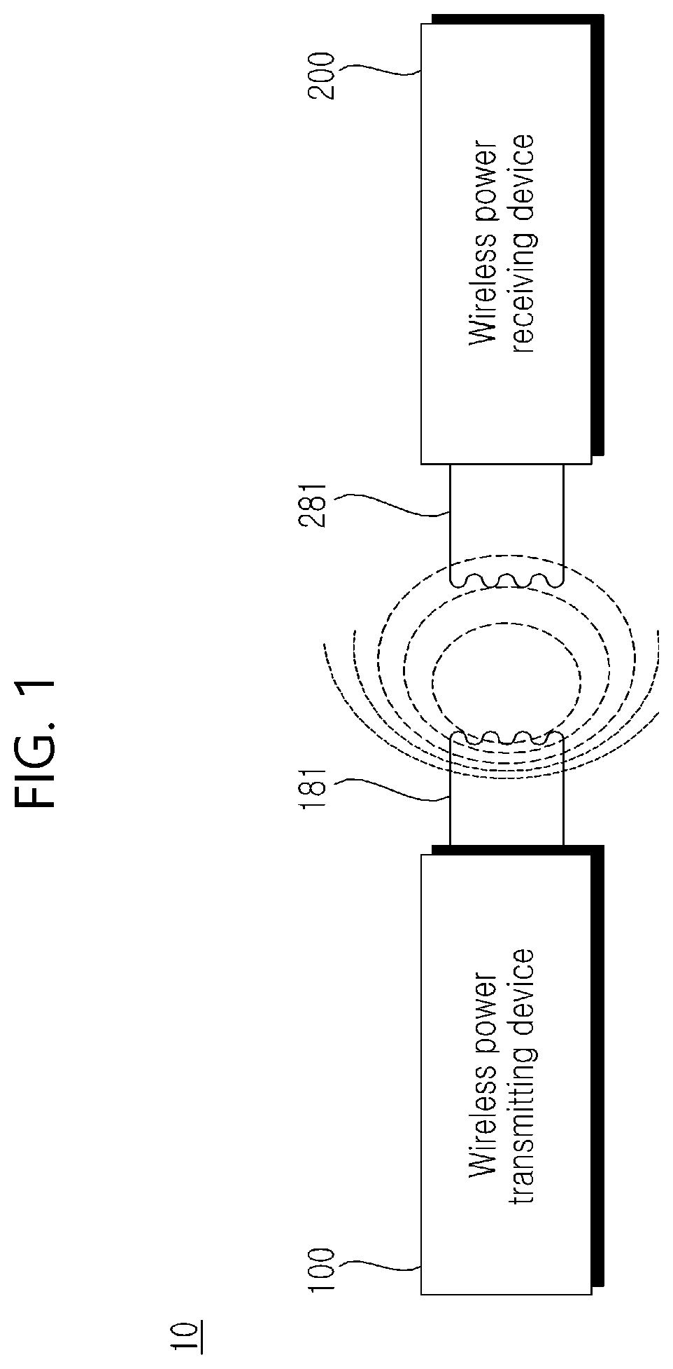
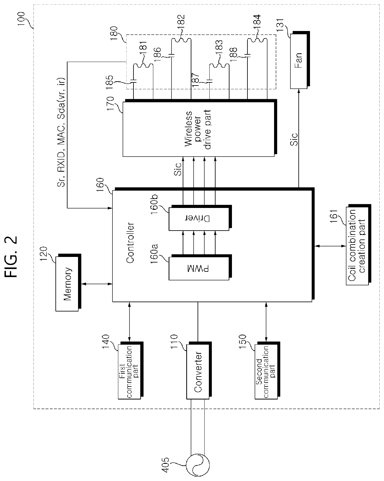
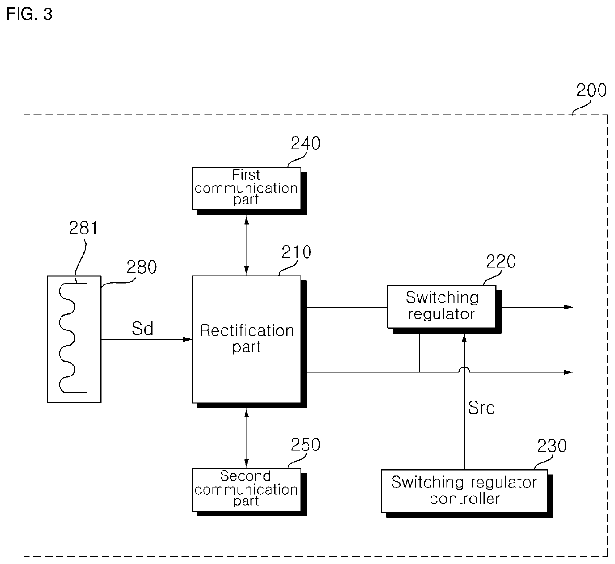
[0028]FIG. 1 shows an example of a...


PUM


Abstract

The present invention relates to a wireless power transmitting device. The wireless power transmitting device comprises a transmitter coil section with a plurality of partially overlapping transmitter coils; a fan for cooling heat generated by the transmitter coil section; and a controller for sending out a detection signal through the transmitter coil section, calculating the number of operating coils based on the strength of a response signal to the detection signal, and controlling the fan based on the calculated number of operating coils. Accordingly, heat generated by the transmitter coils can be reduced more efficiently.

Description

CROSS-REFERENCE TO RELATED APPLICATION[0001]This application claims priority to and the benefit of Korean Patent Application No. 10-2019-0004589 filed in the Korea Intellectual Property Office on Jan. 14, 2019, which is fully incorporated by reference into the present application.BACKGROUND OF THE INVENTIONField of the Invention[0002]The present invention relates to a wireless power transmitting device and, more particularly, to a wireless power transmitting device capable of reducing heat generated by a transmitter coil more efficiently during wireless power transfer.Related Art[0003]Methods for supplying power to an electronic device include a terminal supplying method in which physical cables or wires are connected to a commercial power source and an electronic device. Disadvantages to such a terminal supplying method are that the cables or wires take up a lot of space, are not easy to tidy up, and pose a risk of breakage.[0004]To solve these problems, research on wireless power ...

Claims


Application Information

Patent Timeline
IPC IPC(8): H02J7/00H02J50/80H02J50/40H02J50/12
CPCH02J50/40H02J7/0024H02J50/12H02J50/80H02J7/00309H02J50/402H02J50/10H01F38/14H02J7/00034H01F27/085
Inventor KIM, SUNGKYULEE, SEONGHUNKWAK, BONGSIKLEE, JIHYUNPARK, JOONHO
Owner LG ELECTRONICS INC
Why Eureka
Try Eureka