Fuel cell system and control method of fuel cell system

a fuel cell and control method technology, applied in the direction of fuel cells, reactant parameter control, electrical equipment, etc., can solve problems such as and achieve the effect of curbs deterioration of power generation performance of fuel cells

Inactive Publication Date: 2020-07-30
TOYOTA JIDOSHA KK
View PDF0 Cites 0 Cited by
  • Summary
  • Abstract
  • Description
  • Claims
  • Application Information

AI Technical Summary

Benefits of technology

[0026]According to each aspect of the disclosure, the fuel cell system that curbs deterioration of the power generation performance of the fuel cell, and the control method of the fuel cell system, can be provided.

Problems solved by technology

Accordingly, fuel gas newly injected and fuel gas discharged from the fuel cell cannot be sufficiently mixed with each other, and fuel gas having a uniform concentration cannot be sufficiently diffused into the fuel cell, which may result in deterioration of the power generation performance.

Method used


Image

  • Fuel cell system and control method of fuel cell system
  • Fuel cell system and control method of fuel cell system
  • Fuel cell system and control method of fuel cell system

Examples


Embodiment Construction

Configuration of Fuel Cell System

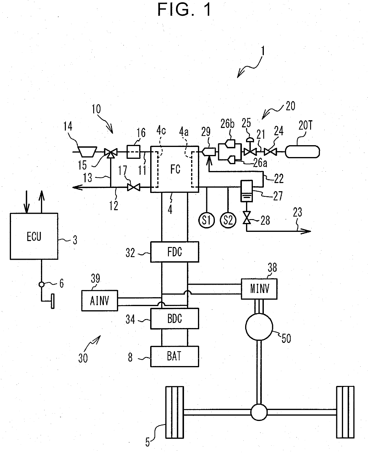
[0034]FIG. 1 shows the configuration of a fuel cell system 1. The fuel cell system 1 is installed on a vehicle, and includes an electronic control unit (ECU) 3, fuel cell (which will be called “FC”) 4, secondary battery (which will be called “BAT”) 8, oxidant gas supply system 10, fuel gas supply system 20, and power control system 30. The fuel cell system 1 includes a cooling system (not shown) that cools the FC 4 by circulating cooling water through the FC 4. Also, the vehicle includes a motor 50 for running the vehicle, wheels 5, and accelerator pedal position sensor 6.

[0035]The FC 4 has a plurality of solid polymer electrolyte type unit cells stacked together, and the unit cells generate electric power when they are supplied with oxidant gas and fuel gas. A cathode channel 4c in which the oxidant gas flows, and an anode channel 4a in which the fuel gas flows, are fat led in the FC 4. Each of the unit cells principally consists of a membrane-elect...


PUM

PropertyMeasurementUnit
injection flow rateaaaaaaaaaa
thresholdaaaaaaaaaa
threshold valueaaaaaaaaaa

Abstract

A fuel cell system includes a fuel cell, a first injector configured to inject fuel gas, a second injector configured to inject the fuel gas at an injection flow rate that is larger than that of the first injector, an ejector mechanism through which the fuel gas injected from each of the first injector and the second injector passes, a supply passage configured to supply the fuel gas passing through the ejector mechanism to the fuel cell, and a circulation passage configured to return the fuel gas discharged from the fuel cell to the ejector mechanism.

Description

INCORPORATION BY REFERENCE[0001]The disclosure of Japanese Patent Application No. 2019-013610 filed on Jan. 29, 2019 including the specification, drawings and abstract is incorporated herein by reference in its entirety.BACKGROUND1. Technical Field[0002]The disclosure relates to a fuel cell system and a control method of the fuel cell system.2. Description of Related Art[0003]A fuel cell system including a first injector that injects fuel gas so that it passes through an ejector, and a second injector that injects the fuel gas at a larger flow rate than the first injector, without causing the gas to pass through the ejector, is known (see Japanese Unexamined Patent Application Publication No. 2014-059969 (JP 2014-059969 A)). The fuel gas injected from the first injector passes through the ejector, so that the fuel gas discharged from the fuel cell is recirculated into the fuel cell, along with the fuel gas injected from the first injector.SUMMARY[0004]According to the technology of ...

Claims


Application Information

Patent Timeline
Patent Type & Authority Applications(United States)
IPC IPC(8): H01M8/04089H01M8/04082H01M8/04119
CPCH01M8/04119H01M8/04201H01M8/04097H01M2008/1095H01M8/04089H01M8/04164H01M8/04604H01M8/04447H01M8/04753Y02E60/50H01M8/04492H01M8/04828
Inventor TANAKA, HIROMI
Owner TOYOTA JIDOSHA KK
Why Eureka
Try Eureka