
Fuel cell separator and fuel cell device

a fuel cell and separator technology, applied in the field of fuel cell separator and fuel cell device, can solve the problems of pitting corrosion, defective parts of tin oxide film, metal oxide possibly generating defective parts, etc., and achieve excellent corrosion resistance and low contact resistance

Active Publication Date: 2021-01-19
TOYOTA JIDOSHA KK +1
View PDF4 Cites 0 Cited by
  • Summary
  • Abstract
  • Description
  • Claims
  • Application Information

AI Technical Summary

Benefits of technology

The patent text describes a fuel cell separator that uses a protective film of tin oxide to reduce chromate diffusion and maintain power generation performance. However, the tin oxide film may contain defects that lead to corrosion and pitting, as well as deterioration of the conductive property of the separator. The disclosed patent aims to provide a fuel cell separator with low contact resistance and excellent corrosion resistance through the use of a tin oxide film.

Problems solved by technology

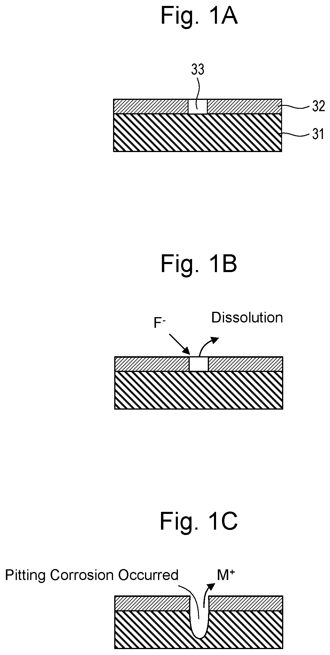
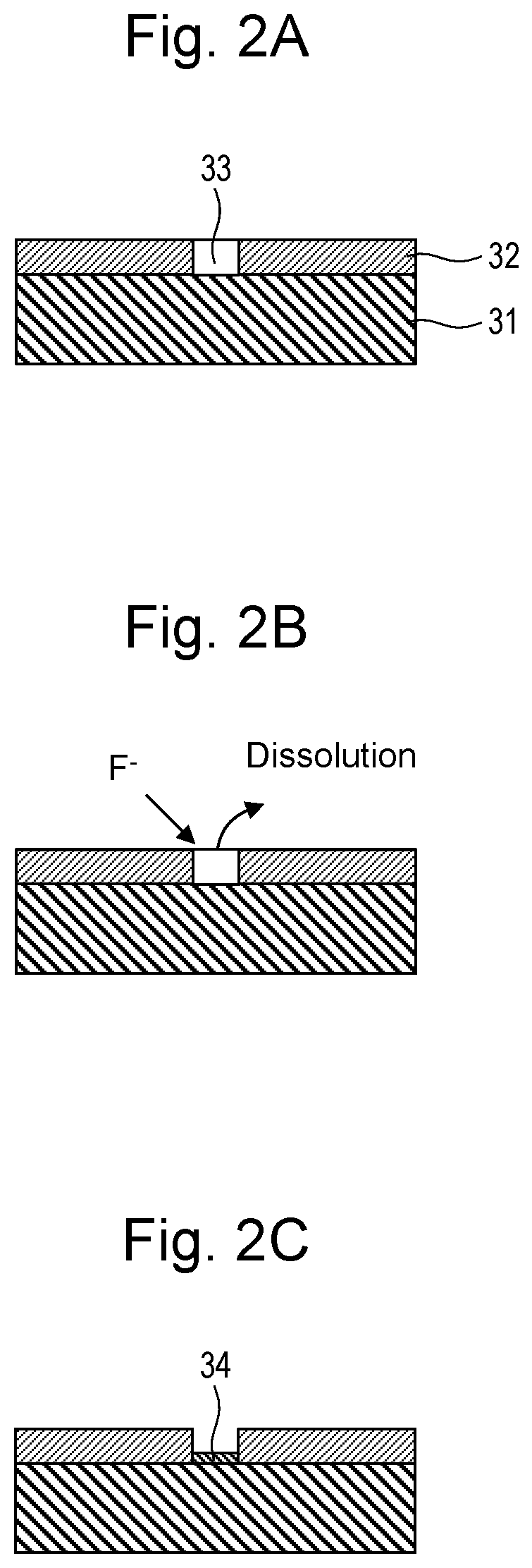
However, formation of a film of the tin oxide on a substrate as the protective film of the metal oxide possibly generates a defective portion (such as a recessed portion where the tin oxide film is not formed) in the tin oxide film.
The defective portion in the tin oxide film has a possibility of causing corrosion under a corrosion environment due to an exposure of a stainless steel substrate and the like.
The dissolution of the metal such as Fe causes pitting corrosion.
Additionally, oxide (insulating property) from the dissolved metal attaches to a surface of the tin oxide film, resulting in deterioration in a conductive property of the separator.
Furthermore, the dissolution of the metal, such as Fe generates hydrogen peroxide with metal ions, such as Fe ions serving as a catalyst (Fenton reaction), possibly causing a disintegration of the solid electrolyte membrane.
The disintegration of the solid electrolyte membrane obviously deteriorates the power generation performance of the fuel cell device.

Method used


Image

  • Fuel cell separator and fuel cell device
  • Fuel cell separator and fuel cell device
  • Fuel cell separator and fuel cell device

Examples


example 1

[0064]A test piece corresponding to the separator was manufactured in accordance with a method described below. First, SUS447 plate having a thickness of 0.1 mm was prepared as the stainless steel substrate of the separator. Next, the stainless steel substrate was installed inside a vacuum container, argon gas was introduced in the vacuum containers under a vacuum condition, a voltage was applied to generate argon ions, and an oxide film on a surface of the stainless steel substrate was removed with these argon ions.

[0065]Next, tin oxide particles and antimony oxide particles were mixed and sintered to produce a sintered body as a target, and the sintered body was disposed in the vacuum container. Targeting this sintered body, a tin oxide film was formed on the surface of the stainless steel substrate by sputtering. Specifically, first, the stainless steel substrate was disposed at a position facing the target, and the vacuum container was vacuated to put the vacuum container under ...


PUM

PropertyMeasurementUnit
thicknessaaaaaaaaaa
thicknessaaaaaaaaaa
thicknessaaaaaaaaaa

Abstract

An object of the present disclosure is to provide a fuel cell separator having a low contact resistance due to a tin oxide film and having an excellent corrosion resistance. An embodiment is a method for manufacturing a fuel cell separator including a stainless steel substrate. The method includes forming the tin oxide film on a surface of the stainless steel substrate; and attaching phosphoric acid or phosphate to at least a defective portion in the tin oxide film.

Description

CROSS REFERENCE TO RELATED APPLICATIONS[0001]The present application claims priority from Japanese patent application JP 2018-122604 filed on Jun. 28, 2018, the content of which is hereby incorporated by reference into this application.BACKGROUNDTechnical Field[0002]The present disclosure relates to a fuel cell separator and a fuel cell device using the same.Background Art[0003]A fuel cell of a solid polymer fuel cell device includes a Membrane Electrode Assembly (MEA), which includes an ion permeable electrolyte membrane, an anode side catalyst layer (electrode layer), and a cathode side catalyst layer (electrode layer). The electrolyte membrane is sandwiched between the anode side catalyst layer and the cathode side catalyst layer. The Membrane Electrode Assembly has both sides on which Gas Diffusion Layers (GDLs) are formed to provide fuel gas or oxidant gas and collect electricity generated through an electrochemical reaction. The Membrane Electrode Assembly having both sides on...

Claims


Application Information

Patent Timeline
Patent Type & Authority Patents(United States)
IPC IPC(8): H01M8/00H01M8/0228H01M8/1039H01M8/0215H01M8/021H01M8/1018
CPCH01M8/0228H01M8/021H01M8/0215H01M8/1039H01M2008/1095H01M2300/0082H01M8/0208Y02P70/50Y02E60/50
Inventor TAKATA, SATOSHIITAGAKI, MASAYUKI
Owner TOYOTA JIDOSHA KK
Learn More